
Vortex generator, fan blade and wind power generator including same

A technology of vortex generators and wind power generators, which is applied in the directions of wind power generators, wind power generators, and wind power generation in the same direction as the wind. Problems such as poor flow separation effect, to achieve the effect of increasing annual power generation, delaying flow stall, and increasing the ability to overcome adverse pressure gradients

Active Publication Date: 2022-03-01
SHANGHAI ELECTRIC WIND POWER GRP CO LTD
View PDF6 Cites 0 Cited by
  • Summary
  • Abstract
  • Description
  • Claims
  • Application Information

AI Technical Summary

Problems solved by technology

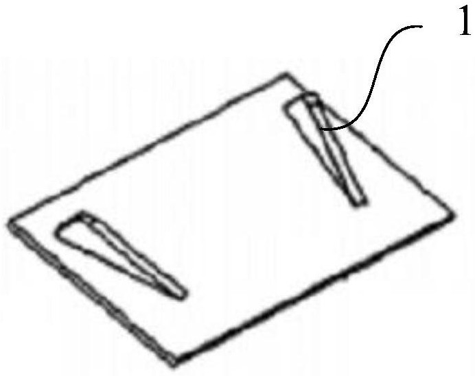
[0006] The fins 1 of the vortex generator are arranged in a "eight" shape, which will lead to an increase in the drag coefficient of the airfoil, thereby affecting the overall power enhancement effect of the vortex generator
[0007] However, if there is no such included angle, the airflow passes over the fin 1 of the vortex generator in parallel, and the downstream vortex structure induced by the fin 1 is very weak, the disturbance to the wake is very limited, and the effect of suppressing flow separation is not good
[0008] In addition, the fin 1 has a limited effect on suppressing flow separation, and the fin 1 has a poor suppressing effect on the flow near the root of the blade with complex three-dimensional flow
[0009] At the same time, the vortex generator of the fin 1 structure is only for inducing turbulence, and its function is too single

Method used


Image

  • Vortex generator, fan blade and wind power generator including same
  • Vortex generator, fan blade and wind power generator including same
  • Vortex generator, fan blade and wind power generator including same

Examples


Embodiment 1

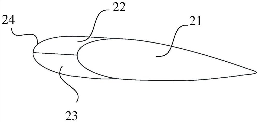
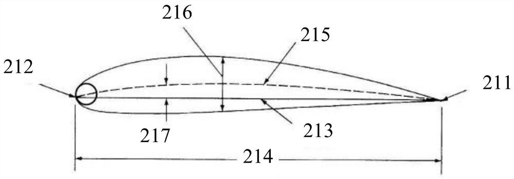
[0091] Such as figure 2 As shown, the present invention provides a vortex generator, including a vortex generating part 2, the vortex generating part 2 includes a front end surface 21, a rear end surface 24, an upper surface 22 and a lower surface 23, and the front end surface 21 is an airfoil. The front end surface 21 , the rear end surface 24 , the upper surface 22 and the lower surface 23 of the vortex generating part 10 are directly connected to form a closed space. By using the airfoil as the vortex generating part 2 of the vortex generator, the flow resistance caused by the introduction of the vortex generator itself is reduced; at the same time, after the fluid flows through the airfoil, its wake contains many high-energy wake vortices, which generate enough Wing tip vortices, thereby inhibiting or delaying flow separation on the airfoil surface. The vortex generator can effectively delay the flow stall on the airfoil surface, delay the stall attack angle by about 2-1...

Embodiment 2

[0098] Such as Figure 4 As shown, the structure of this embodiment is basically the same as that of Embodiment 1, the difference being:

[0099] The vortex generator of this embodiment adds a supporting part, and the supporting part is directly connected with the lower surface 23 of the vortex generating part 2 . Specifically, the supporting portion in this embodiment is a supporting plate, specifically a single supporting plate 31 . The number of single support plate 31 is one, and the single support plate 31 is parallel to the front end surface 21 of the vortex generating part 2 , is located in the middle of the front end surface 21 , and is directly connected with the lower surface 23 . By increasing the supporting part, the flexibility of positioning the vortex generator is improved, the vortex generator can be easily installed to a required position, and the installation height, angle, etc. can be adjusted conveniently.

Embodiment 3

[0101] Such as Figure 5 As shown, the structure of this embodiment is basically the same as that of Embodiment 2, the difference being:

[0102] In this embodiment, the support portion for eddy current generation is designed as double parallel plates 32 , and the number of double parallel plates 32 is 2 pieces, which are directly connected to the front end face 21 respectively. By adopting such a structural form of the supporting part, the stability of the vortex generator is improved, and the installation angle of the vortex generating part of the vortex generator is also convenient to be adjusted.


PUM


Abstract

The invention discloses a vortex generator, a fan blade and a wind generator comprising the same. The vortex generator includes a vortex generating part, the vortex generating part includes an upper surface, a lower surface, a front end surface and a rear end surface, the front end surface and the rear end surface are airfoils, and the surfaces of the vortex generating part are directly connected to form a closed space. By using the airfoil as the vortex generating part, the flow resistance caused by the introduction of the vortex generator itself is reduced. At the same time, after fluid flows through the airfoil, wake vortex and wingtip vortex can be generated, which can effectively resist or delay flow separation. The vortex generator of the invention can also delay the airfoil surface flow stall attack angle by 2°-10°, and increase the lift-to-drag ratio by 30%-300%. In addition, the vortex generator can also generate lift. The fan blades and wind generators equipped with this type of vortex generator can effectively increase the annual power generation by about 1% to 6%. For wind farms in low wind speed areas and low air density areas, It is better to increase the power generation.

Description

technical field [0001] The invention relates to the technical field of wind power generation, in particular to a vortex generator, a fan blade and a wind power generator including the same. Background technique [0002] Wind energy is the kinetic energy produced by the movement of air. The total reserves of wind energy resources are huge, and the energy that can be developed by technology in a year is about 5.3X10^13 kWh. Wind energy is a renewable clean energy with large reserves and wide distribution. A wind generator, also called a fan, is an electrical device that converts wind energy into mechanical work, which drives the rotor to rotate, and finally outputs alternating current. [0003] A number of vortex generators are usually installed on the surface of the blades of modern wind turbines. Usually, the vortex generators are installed on the suction side of the blade and located in the boundary layer to increase the disturbance of the boundary layer and replenish ene...

Claims


Application Information

Patent Timeline
Patent Type & Authority Patents(China)
IPC IPC(8): F03D1/06
CPCF03D1/0675F05B2260/97F05B2260/96Y02E10/72
Inventor 艾国远李海涛赵大文
Owner SHANGHAI ELECTRIC WIND POWER GRP CO LTD
Learn More