Building vibration monitoring system based on household communication optical cable

A technology of vibration monitoring system and communication optical cable, applied in signal transmission system, non-electrical signal transmission system, measuring device, etc., can solve the problem that private decoration is difficult to find, community property and housing management department is difficult to supervise and manage, house structure reliability and earthquake resistance Performance impact and other issues, to avoid re-laying, high sensitivity, small fiber volume

Pending Publication Date: 2020-08-07
武汉地震工程研究院有限公司
View PDF0 Cites 0 Cited by
  • Summary
  • Abstract
  • Description
  • Claims
  • Application Information

AI Technical Summary

Problems solved by technology

The demolition and modification of the load-bearing components of the house has affected the reliability and seismic performance of the entire house structure, and it is difficult to find out the private decoration, which brings certain difficulties to the supervision and management of the property and housing management departments of the community
[0003] At present, there are few sensors specially installed for earthquake monitoring in buildings. Once an earthquake occurs, it can only be judged by personal experience or rely on early warning notices from relevant departments. Especially when an earthquake comes at night, it is difficult for sleeping residents to detect the earthquake in time.

Method used


Image

  • Building vibration monitoring system based on household communication optical cable
  • Building vibration monitoring system based on household communication optical cable

Examples


Embodiment Construction

[0025] In conjunction with the accompanying drawings, the technical solution of the present invention is further described through specific embodiments.

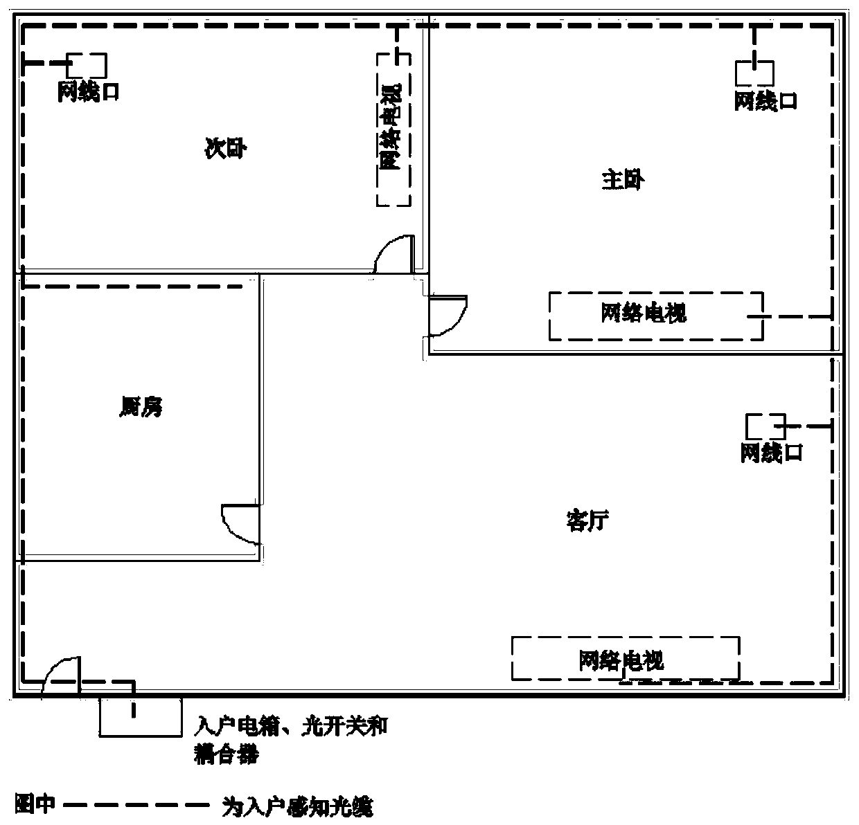
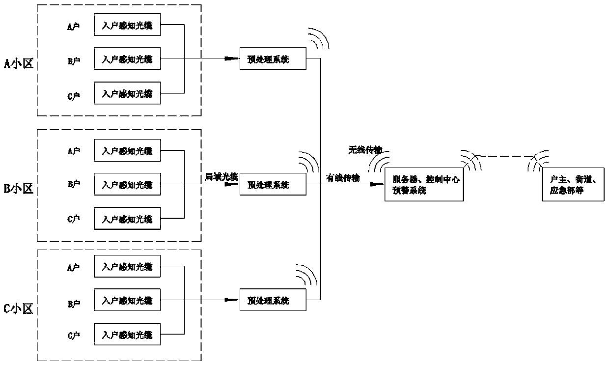
[0026] A building vibration monitoring system based on a household communication optical cable, comprising a household sensing optical cable, a local area transmission optical cable, a preprocessing system, a remote transmission system and a remote control center, and the household sensing optical cable utilizes an existing household communication optical cable As an optical fiber sensor to perceive the vibration caused by fire and illegal transformation, the local transmission optical cable is a communication optical cable in the community, which transmits the sensing signal to the preprocessing system, and upgrades the original communication room, and sets Φ-OTDR distributed optical fiber transmission The remote transmission system is responsible for transmitting the monitoring data of the community to the remote control ce...


PUM


Abstract

The invention discloses a building vibration monitoring system based on a household communication optical cable. The building vibration monitoring system comprises a home-entry sensing optical cable,a local transmission optical cable, a preprocessing system, a remote transmission system and a remote control center. The home-entry sensing optical cable is a household communication optical cable and is used for building vibration monitoring, the local area transmission optical cable is an intra-cell communication optical cable and transmits a sensing signal to the preprocessing system, and thepreprocessing system is arranged in an original communication machine room and is composed of a phi-OTDR distributed optical fiber sensing system. The remote transmission system is divided into the wireless transmission or wired transmission, and the remote control center comprises a server and a remote early warning system, further processes the monitoring data, and sends an early warning notification in the form of a short message and the like if the monitoring data exceeds an early warning threshold. According to the present invention, an existing household communication optical cable is adopted, and through the high sensitivity and a positioning function of the optical fiber sensing, the purposes of earthquake, natural vibration frequency and violation reconstruction vibration monitoring of a building are achieved, and the huge economic value, social value and application prospect are achieved.

Description

technical field [0001] The invention belongs to the fields of structural health monitoring and optical fiber sensing, and in particular relates to a building vibration monitoring system based on household communication optical cables. Background technique [0002] Incidents of demolishing and modifying houses happen all the time. Due to lack of professional knowledge and weak safety awareness, many owners demolish and modify the load-bearing components of houses without design and application, resulting in safety accidents. The demolition and modification of the load-bearing components of the house has affected the reliability and seismic performance of the entire house structure, and it is difficult to find out the private decoration, which brings certain difficulties to the supervision and management of the community property and housing management departments. [0003] At present, there are few sensors specially installed for earthquake monitoring in buildings. Once an ea...

Claims


Application Information

Patent Timeline
Patent Type & Authority Applications(China)
IPC IPC(8): G01H9/00G08C23/06
CPCG01H9/004G08C23/06
Inventor 张作才冯谦王浩谭杰梁亚斌
Owner 武汉地震工程研究院有限公司
Why Eureka
Try Eureka