
High-voltage switch cabinet partial discharge positioning detection system and detection method

A high-voltage switchgear and partial discharge technology, which is applied in the direction of measuring electricity, measuring devices, and test circuits, can solve the problems of high device cost, affecting the efficiency of operation and maintenance, and it is difficult for operation and maintenance personnel to judge the location of partial discharge. Positioning accuracy, improved detection efficiency, simple and easy positioning process

Active Publication Date: 2020-08-07
STATE GRID CORP OF CHINA +2
View PDF7 Cites 6 Cited by
  • Summary
  • Abstract
  • Description
  • Claims
  • Application Information

AI Technical Summary

Problems solved by technology

[0004]However, due to the randomness of partial discharge, the detection results will fluctuate within a certain range. Judging the location of partial discharge affects the efficiency of operation and maintenance
At present, some scholars have proposed to use a comprehensive detection method to locate the switchgear with partial discharge, that is, to use TEV, ultrasonic, UHF and temperature detection methods, which have achieved certain application effects, but the overall high cost of the device limits its application. Promotion and application in the grid
Some scholars use the traveling wave method to locate the partial discharge of the switchgear, which can accurately locate the precise position of the partial discharge. However, because the high-speed acquisition card is required to reach above GHz, the cost of the device is very high, and it is difficult to achieve a wide range of industrial applications.

Method used


Image

  • High-voltage switch cabinet partial discharge positioning detection system and detection method
  • High-voltage switch cabinet partial discharge positioning detection system and detection method
  • High-voltage switch cabinet partial discharge positioning detection system and detection method

Examples


Embodiment Construction

[0035] The present invention is described in further detail below in conjunction with accompanying drawing:

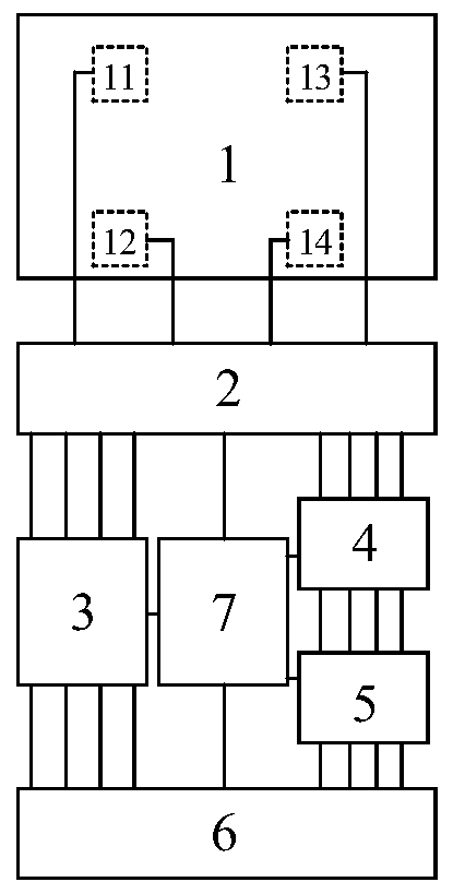
[0036] Such as figure 1 As shown, a high-voltage switchgear partial discharge location detection system of the present invention includes a TEV sensor group unit 1, a filter amplification unit 2, a pulse source direction judgment unit 3, a control processing unit 6, and a power supply unit 7; the power supply unit 7 is used for System power supply;

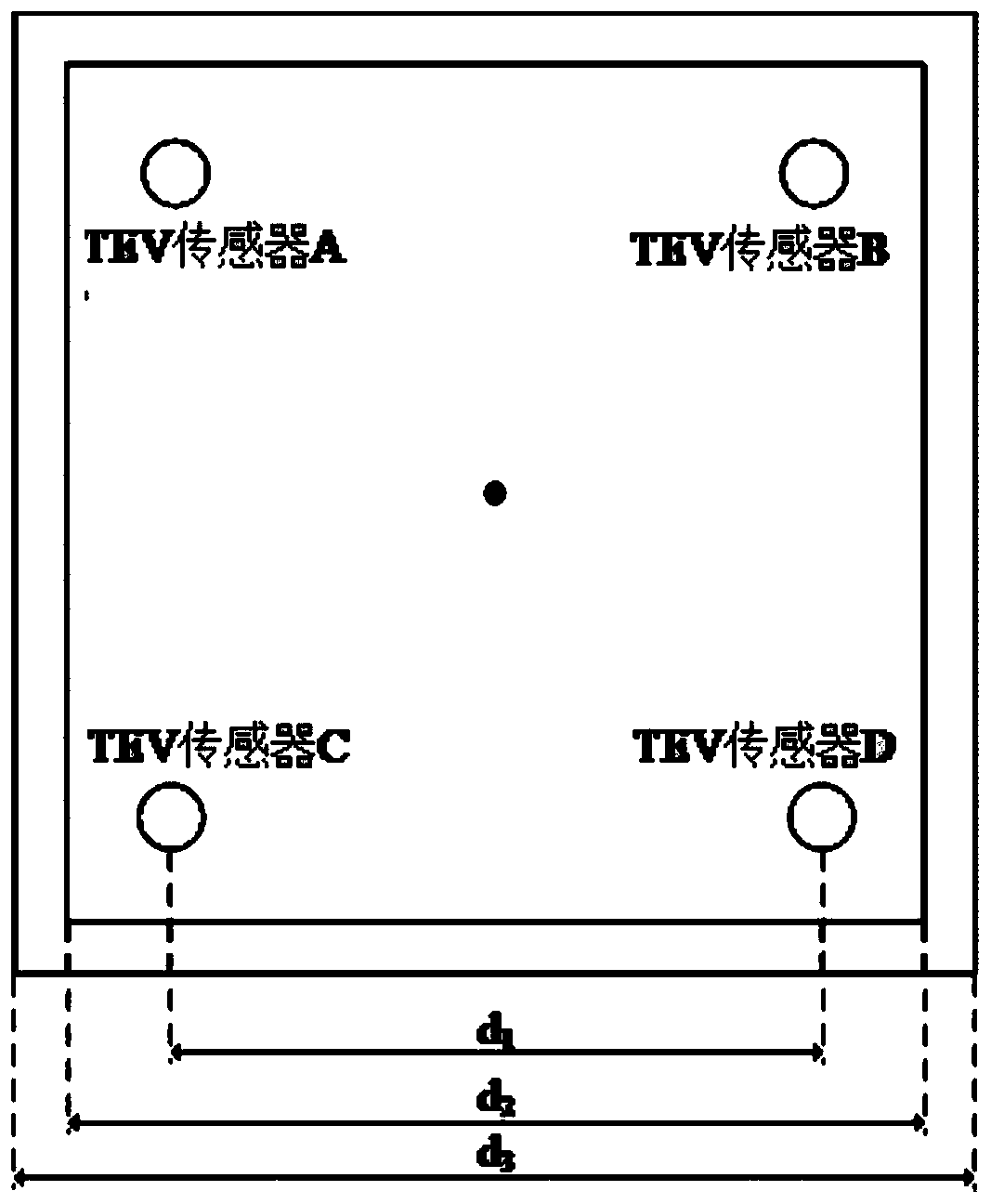
[0037] The TEV sensor group unit 1 includes four TEV sensors, and the centers of the four TEV sensors are sequentially connected to form a square. The TEV sensors are used to collect partial discharge pulse signals, and send the collected partial discharge pulse signals to the filtering and amplifying unit 2;

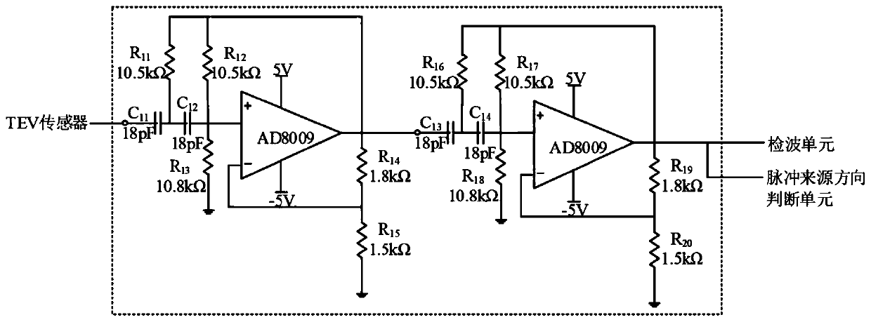
[0038] The filtering and amplifying unit 2 filters and amplifies the partial discharge pulse signal transmitted by each TEV sensor, and then transmits it to the pulse source direction judging unit 3;

[0039] The ...


PUM

PropertyMeasurementUnit
Frequencyaaaaaaaaaa
Bandwidthaaaaaaaaaa

Abstract

The invention discloses a high-voltage switch cabinet partial discharge positioning detection system and detection method. Four TEV sensors are adopted to form a sensor group. Partial discharge signals of four positions of the cabinet surface of the high-voltage switch cabinet are collected in a square arrangement mode. A pulse source direction judging unit is combined to judge the sequence of thepartial discharge pulses reaching the four TEV sensors so as to judge the source direction of the partial discharge pulse signal; partial discharge pulse signals are obtained in a square arrangementmode that four TEV sensors form a sensor group in a fast and concise manner, software processing does not need to be carried out on the partial discharge pulse signal; the pulse source direction judgment unit is used for judging the arrival sequence of the TEV sensor signals, and the sensor signals do not need to be compared through a software method any more, so that the use of an ultrahigh-speedacquisition chip is avoided, the positioning work is facilitated, the working process is simplified, the detection efficiency is improved, and the positioning accuracy is improved.

Description

technical field [0001] The invention belongs to the field of partial discharge pre-location of high-voltage switch cabinets, and in particular relates to a local discharge detection system and detection method of high-voltage switch cabinets. Background technique [0002] High-voltage switchgear is a kind of power equipment integrating measurement, control and protection functions. It is widely installed in power plants and substations in the power system, so it plays a vital role in the safety of the power grid. Due to the limitations of the production process and the long-term impact of installation and operation, various forms of partial discharge will be formed in the switchgear, and may cause a series of insulation failures. According to incomplete statistics, the number of accidents caused by insulation failure of switchgear accounts for 68% of the total number of switchgear accidents and 74% of the total accident capacity, which is the main cause of switchgear acciden...

Claims


Application Information

Patent Timeline
IPC IPC(8): G01R31/12G01R31/14
CPCG01R31/1227G01R31/14Y04S10/52
Inventor 张航伟任双赞郝东新刘晶牛博吴昊杨传凯颜源李洪杰
Owner STATE GRID CORP OF CHINA
Learn More