Voltage stabilizer structure with system connecting pipe and electric heating element centrally arranged on upper portion and application thereof
A technology of electric heating elements and voltage stabilizers, which is applied in the directions of reactors, nuclear power generation, cooling devices, etc., can solve problems such as unfavorable overall performance, and achieve the effects of optimizing nuclear power system layout, realizing space integration, and optimizing structure
- Summary
- Abstract
- Description
- Claims
- Application Information
AI Technical Summary
Problems solved by technology
Method used
Image
Examples
Embodiment 1
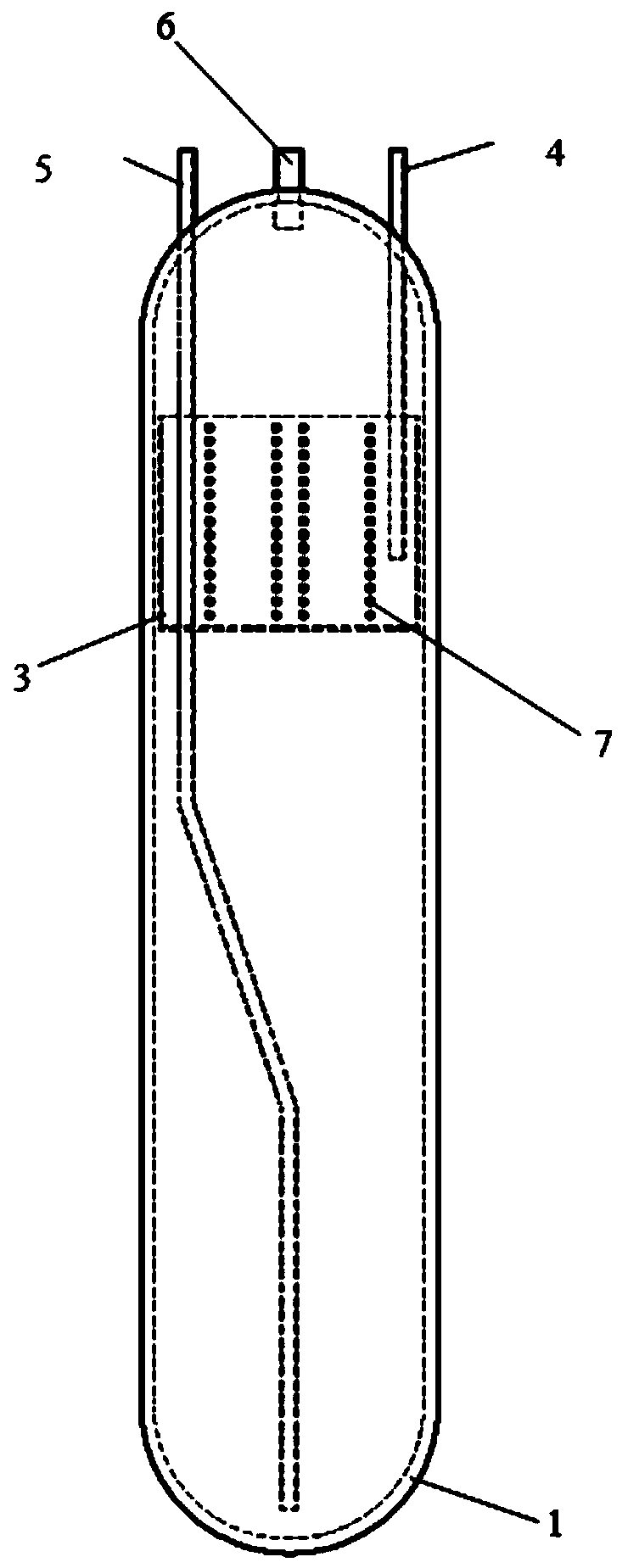
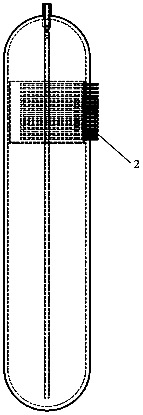
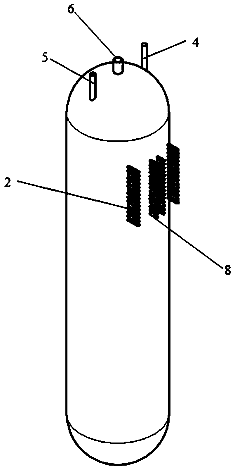
[0036] This embodiment proposes a voltage stabilizer structure in which the system nozzle and the upper part of the electric heating element are centrally arranged. The structure includes a cylinder 1, an electric heating element 2 and a nozzle assembly; wherein, the electric heating element and the nozzle assembly are arranged on the upper part of the cylinder.
[0037] Compared with the existing general voltage stabilizer structure, the present invention simplifies the layout requirements and difficulty of the lower voltage stabilizer by centrally arranging the electric heating element and the system takeover on the upper part of the voltage stabilizer, and at the same time, the pressure control and volume compensation of the system can be realized. function, the present invention optimizes the overall performance of the system.
[0038] Specifically in this embodiment, as Figure 1-3 As shown, the structure of the voltage stabilizer is a cylindrical cylindrical structure. ...
Embodiment 2
[0042] The system takeover and the pressure stabilizer structure centrally arranged on the upper part of the electric heating element proposed in the above embodiment 1 are used in the pressure safety system connected with the nuclear reactor system, so as to realize the pressure safety control of the nuclear reactor coolant system.
[0043] When the system needs to heat up and generate a steam chamber, the electric heating element 2 is activated, and the water supply pipe 4 is continuously filled with water. Due to the heating effect of the electric heating element 2 in the water tank 3, the temperature of the medium inside the pressure stabilizer rises and the volume increases, and the wave pipe 5 drains water to the reactor coolant system; at the same time, steam is continuously generated inside the pressure stabilizer cylinder 1, and the system steam vapor is established. cavity. When the system needs to cool down and eliminate the steam cavity, it is completed through the...
Embodiment 3
[0045] The system connection pipe and the pressure stabilizer structure centrally arranged on the upper part of the electric heating element proposed in the above embodiment 1 can also be applied to the pressure safety system connected with the high temperature and high pressure systems in other technical fields to realize the pressure safety control.
[0046] As will be appreciated by those skilled in the art, the embodiments of the present application may be provided as a method, a system, or a computer program product. Accordingly, the present application may take the form of an entirely hardware embodiment, an entirely software embodiment, or an embodiment combining software and hardware aspects. Furthermore, the present application may take the form of a computer program product embodied on one or more computer-usable storage media having computer-usable program code embodied therein, including but not limited to disk storage, CD-ROM, optical storage, and the like.
PUM
 Abstract
Description
Claims
Application Information
 - R&D
- Intellectual Property
- Life Sciences
- Materials
- Tech Scout
- Unparalleled Data Quality
- Higher Quality Content
- 60% Fewer Hallucinations
Browse by: Latest US Patents, China's latest patents, Technical Efficacy Thesaurus, Application Domain, Technology Topic, Popular Technical Reports.
© 2025 PatSnap. All rights reserved.Legal|Privacy policy|Modern Slavery Act Transparency Statement|Sitemap|About US| Contact US: help@patsnap.com


