PVC communication optical fiber cable protection sleeve convenient to sleeve

A cable protection sleeve, communication optical fiber technology, applied in the cable installation in the ground conduit, the cable installation in the underground pipeline, the cable installation, etc. Anti-slippage, high stability and high oxidation resistance

Active Publication Date: 2020-08-07
邵春牛
View PDF14 Cites 4 Cited by
  • Summary
  • Abstract
  • Description
  • Claims
  • Application Information

AI Technical Summary

Problems solved by technology

The above-mentioned patents have the following disadvantages: when the cable is inserted into the sleeve, there is only friction between the cable and the sleeve, and when the inner diameter of the sleeve is com

Method used


Image

  • PVC communication optical fiber cable protection sleeve convenient to sleeve
  • PVC communication optical fiber cable protection sleeve convenient to sleeve
  • PVC communication optical fiber cable protection sleeve convenient to sleeve

Examples


Embodiment 1

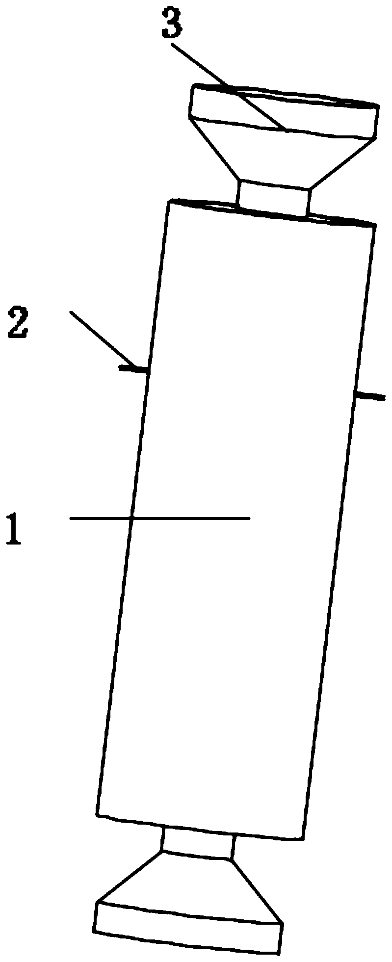
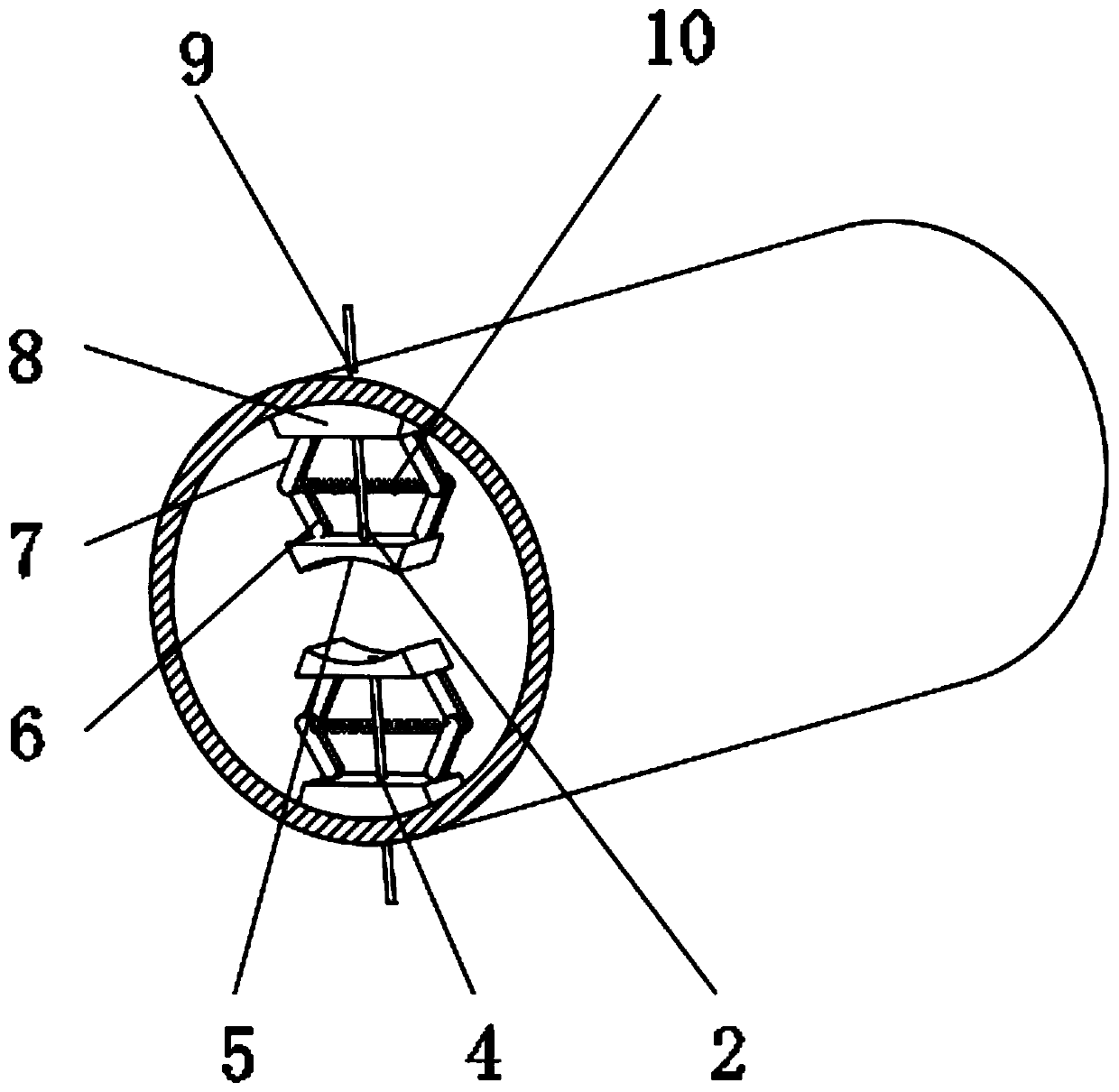
[0029] A protective sleeve for PVC communication optical fiber cables that is easy to set, such as figure 1 , 2 As shown, it includes a sleeve main body 1 and a sealing joint 3 used in conjunction with the sleeve main body 1. The two sealing joints 3 are respectively symmetrically matched to the two end faces of the sleeve main body 1, and the sleeve main body 1 is close to the two ends. The inner walls of each end face are provided with a clamping assembly, and the distance between the clamping assembly and the end face of the casing main body 1 is greater than the width of the sealing joint 3; when in use, first put the sealing joint 3 on the cable, and then plug the cable into into the casing main body 1, and slowly tighten the cable so that the sealing joint 3 is completely embedded in the inner wall of the casing main body 1. After reaching the desired position, put another sealing joint 3 on the cable and slide slowly so that Two sealing joints 3 are respectively embedd...

Embodiment 2

[0039] A protective sleeve for PVC communication optical fiber cables that is easy to set, such as figure 1 , 2 As shown, it includes a sleeve main body 1 and a sealing joint 3 used in conjunction with the sleeve main body 1. The two sealing joints 3 are respectively symmetrically matched to the two end faces of the sleeve main body 1, and the sleeve main body 1 is close to the two ends. The inner walls of each end face are provided with a clamping assembly, and the distance between the clamping assembly and the end face of the casing main body 1 is greater than the width of the sealing joint 3; when in use, first put the sealing joint 3 on the cable, and then plug the cable into into the casing main body 1, and slowly tighten the cable so that the sealing joint 3 is completely embedded in the inner wall of the casing main body 1. After reaching the desired position, put another sealing joint 3 on the cable and slide slowly so that Two sealing joints 3 are respectively embedd...


PUM

PropertyMeasurementUnit
Outer diameteraaaaaaaaaa
Diameteraaaaaaaaaa

Abstract

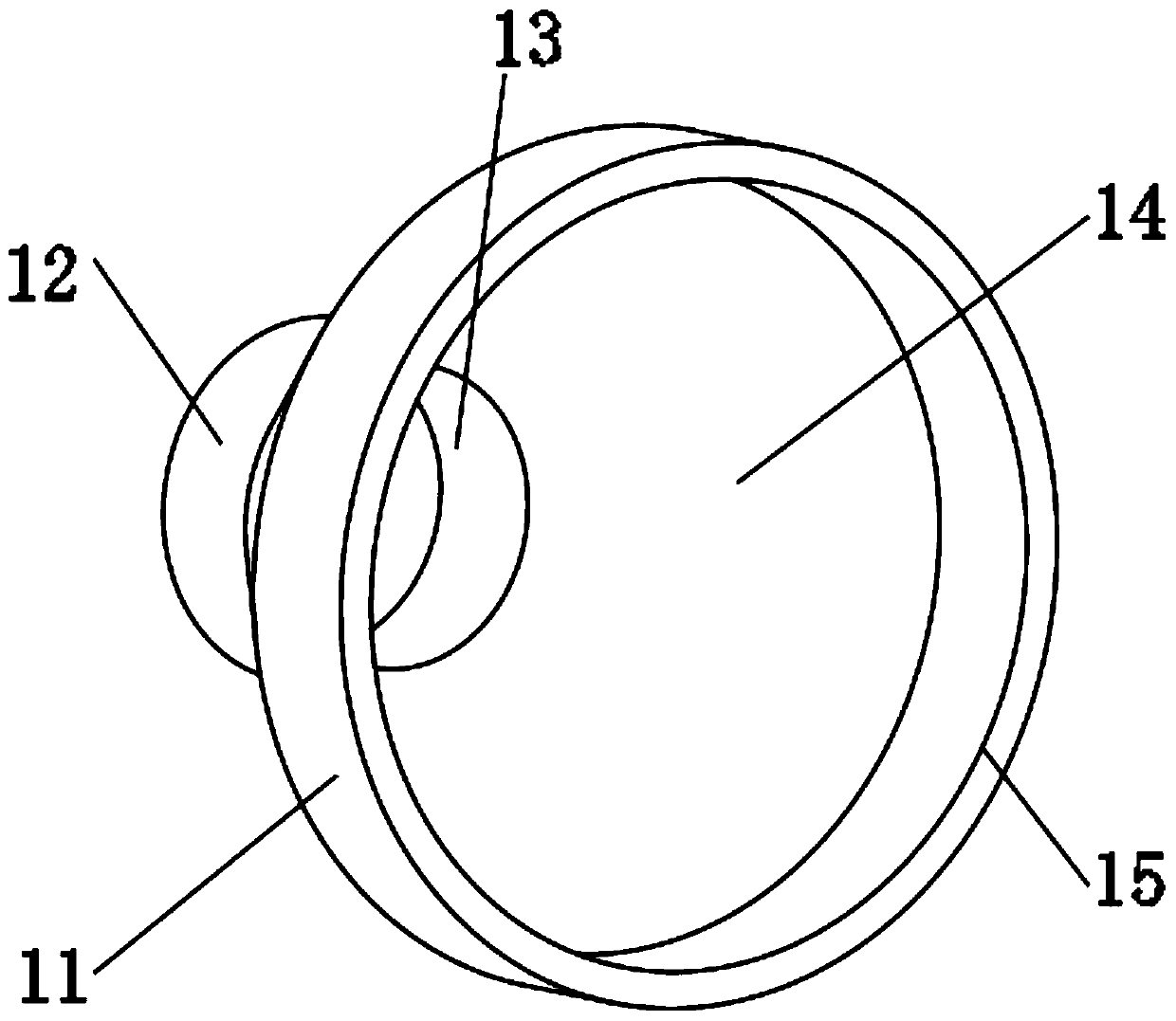
The invention discloses a PVC communication optical fiber cable protection sleeve convenient to sleeve, and relates to the technical field of protection sleeves, and aims to solve the problem of slippage. The sleeve specifically comprises a casing pipe main body and a sealing joint matched with the casing pipe main body for use, two sealing joints are respectively and symmetrically matched with two end surfaces of the sleeve main body for use, clamping assemblies are arranged on the inner walls, close to the two end surfaces, of the sleeve main body, and each sealing joint comprises a cable sheath, a transition sleeve, a sleeve bushing, and an inner sealing surface and an outer sealing surface which are arranged on the outer wall of the sleeve bushing. According to the invention, the clamping assembly is arranged; when a cable is threaded in, the two clamping blocks can be separated from each other by pulling the two stay wires, the stay wires are loosened after the cable is threaded in, and the hinged positions of a first hinge rod and a second hinge rod are close to each other under the tension action of the spring at the moment, so that the two clamping blocks are close to eachother until the cable is firmly clamped, and the sleeve main body can be effectively prevented from slipping off.

Description

technical field [0001] The invention relates to the technical field of protective sleeves, in particular to a PVC communication optical fiber cable protective sleeve which is convenient for fitting. Background technique [0002] Cable protection sleeve is a new type of sleeve material popularized and used in electric power engineering. With the rapid development of buried power cable laying projects, higher requirements are put forward for cable sleeves. Cable protection sleeves are made of polyethylene PE and High-quality steel pipes are made by pre-treatment of sandblasting and shot blasting, dipping or coating and heating and curing processes. It is the most commonly used electrical insulation pipe for protecting wires and cables because of its good insulation performance, high chemical stability, It is widely used because it does not rust, does not age and can adapt to harsh environments. [0003] After searching, the Chinese Patent Publication No. is CN205829072U, whic...

Claims


Application Information

Patent Timeline
IPC IPC(8): H02G3/06H02G3/04H02G9/04H02G9/06
CPCH02G3/04H02G3/06H02G9/04H02G9/06
Inventor 邵春牛
Owner 邵春牛
Why Eureka
Try Eureka