Petroleum extraction device for petroleum residues

An extraction device, oil technology, applied in the direction of filtration separation, separation method, mobile filter element filter, etc., can solve the problems of poor separation effect and waste of residue

Inactive Publication Date: 2020-08-11
李君毅
View PDF1 Cites 3 Cited by
  • Summary
  • Abstract
  • Description
  • Claims
  • Application Information

AI Technical Summary

Problems solved by technology

This kind of petroleum residue oil extraction device has simple structure, convenient operation, strong functionality, and novel design. Through the mutual cooperation between the roller and the scraper, the oil in the petroleum residue can be better diluted, avoiding material waste, improve the efficiency of oil extraction, save a lot of costs, and improve work efficiency; by setting the mutual

Method used


Image

  • Petroleum extraction device for petroleum residues
  • Petroleum extraction device for petroleum residues
  • Petroleum extraction device for petroleum residues

Examples


Embodiment 1

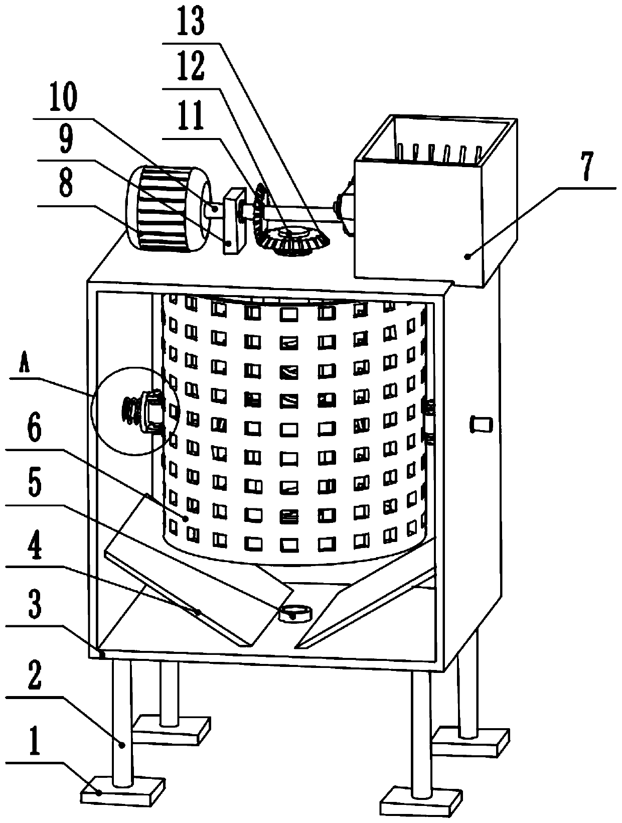
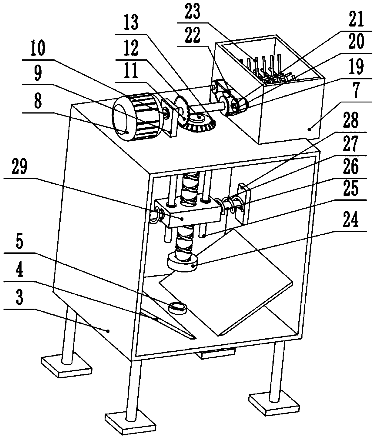
[0027] see Figure 1-4 , a petroleum extraction device for petroleum residues, comprising a separation box 3, the middle part of the lower surface of the separation box 3 is provided with an oil discharge port 5, the left side of the upper surface of the separation box 3 is provided with a drive motor 8, and the output shaft of the drive motor 8 is fixed Connect the left end of the rotating shaft 10, the middle part of the rotating shaft 10 is provided with a first bevel gear 11, the first bevel gear 11 meshes with the second bevel gear 13, the second bevel gear 13 is fixedly connected to the upper end of the rotating rod 12, and the upper part of the rotating rod 12 rotates Connect the upper part of the crushing box 7, the middle part of the rotating rod 12 is threaded to connect the lifting block 29, and the bottom of the rotating rod 12 is provided with a double helical chute, so when the rotating rod 12 rotates, the lifting block 29 moves up and down along the double helica...

Embodiment 2

[0030] see figure 1 , the other content of this embodiment is the same as that of Embodiment 1, except that: the lower part of the left and right side walls of the separation box 3 is provided with a deflector 4 . Due to the high viscosity of oil, in order to avoid oil deposition inside the device, two inclined deflectors 4 are set at the bottom of the device, through which the oil can gather in the middle of the bottom of the device and pass through the oil outlet 5 discharge.

[0031]In the implementation process of the present invention, the drive motor 8 is started, and the output shaft of the drive motor 8 drives the rotating shaft 10 to rotate, and the rotating shaft 10 drives the two crushing shafts 20 to rotate through the first pulley 19, the belt 22 and the second pulley 21, and the crushing shaft 20 drives the crushing rod 23 to rotate at a high speed. At this time, the petroleum residue that needs to be further purified is put into the crushing box 7. The petroleu...


PUM


Abstract

The invention relates to the technical field of petroleum extraction, and discloses a petroleum extraction device for petroleum residues. The device comprises a separation box; an oil outlet is formedin the middle of the lower surface of the separation box; a crushing box is arranged on the right side of the upper surface of the separation box; rotating wheels on the front and rear sides of the crushing box are connected with a crushing shaft; a crushing rod is arranged in the middle of the crushing shaft; a driving motor is arranged on the left side of the upper surface of the separation box; an output shaft of the driving motor is fixedly connected with the left end of a rotating shaft; a first bevel gear is arranged in the middle of the rotating shaft and engaged with a second bevel gear; the second bevel gear is fixedly connected with the upper end of a rotating rod; the middle of the rotating rod is in threaded connection with a lifting block; the left and right ends of the lifting block are slidably connected with second sliding rods; scrapers are arranged at the ends of the second sliding rods; and second springs are arranged between the scrapers and the lifting block. According to the petroleum extraction device suitable for petroleum residues, a separation barrel rotating at a high speed is arranged, so that the petroleum residues are subjected to the action of centrifugal force, and the petroleum residues are separated from petroleum.

Description

technical field [0001] The invention relates to the technical field of oil extraction, in particular to an oil extraction device for oil residue. Background technique [0002] Petroleum refers to a mixture of gaseous, liquid and solid hydrocarbons in natural occurrence. Petroleum is divided into crude oil, natural gas, natural gas liquid and natural tar, etc., but it is customary to use "oil" as the definition of "crude oil". [0003] Petroleum must be processed before use to make petroleum products suitable for various purposes. In industry, the oil is first heated to between 400°C and 500°C to make it into vapor and then enter the fractionation tower. In a fractionation column, the higher the position, the lower the temperature. Petroleum vapor gradually liquefies, cools and condenses into liquid fractions as it rises. The gaseous fraction with smaller molecules and lower boiling point slowly rises up the tower and condenses at the upper level of the tower. The liquid...

Claims


Application Information

Patent Timeline
IPC IPC(8): B01D33/11B01D33/46
CPCB01D33/11B01D33/466
Inventor 李君毅
Owner 李君毅
Why Eureka
Try Eureka