[0024] The following will clearly and completely describe the technical solutions in the embodiments of the present invention with reference to the accompanying drawings in the embodiments of the present invention. Obviously, the described embodiments are only some, not all, embodiments of the present invention.
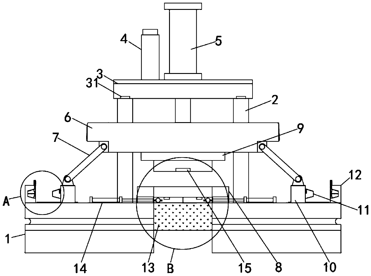
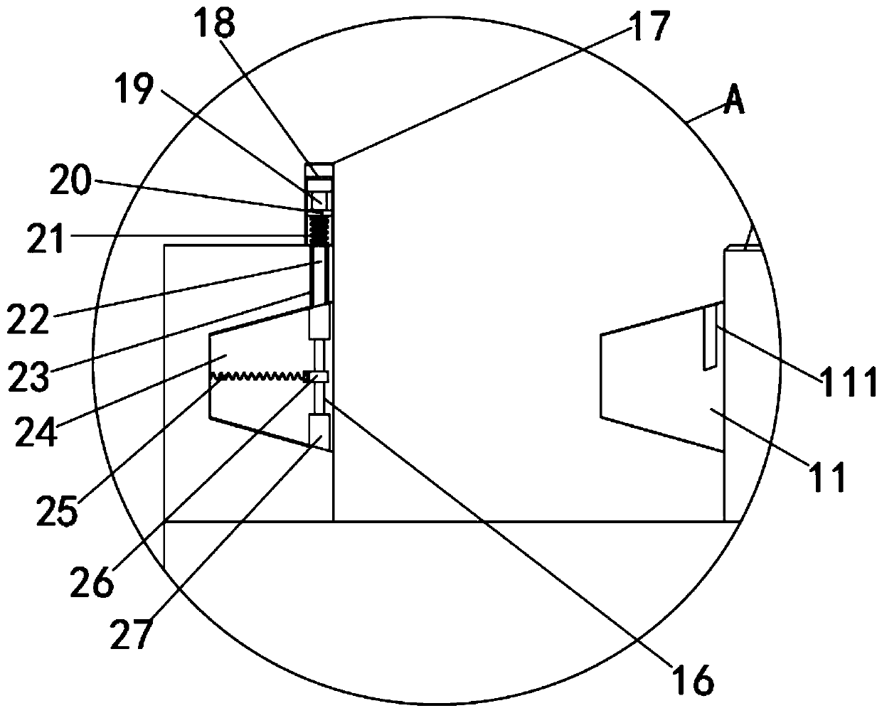
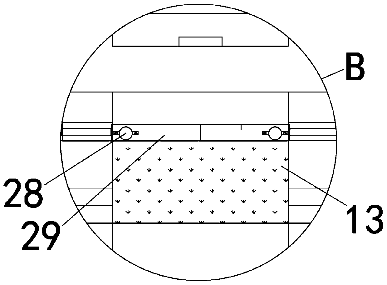
[0025] refer to Figure 1-3 , a stator-rotor iron core mold automatic bonding stamping die, including a base 1, the top of the base 1 is respectively fixed with a lower die 8, symmetrically arranged guide pillars 2 and a fixed plate 12 by bolts, and the top of the guide pillar 2 The top plate 3 is fixedly installed, and the outside of the guide column 2 is slidably provided with a lifting pressure plate 6. The bottom of the top plate 3 is equipped with a first pressure sensor 31, and the top of the top plate 3 is respectively fixedly installed with a pressure monitor 4 and a driving cylinder 5. The inside of the cylinder 5 is provided with a first piston rod, and the other end of the first piston rod is fixedly connected with the top of the lifting pressure plate 6 through nuts and bolts. There is a second pressure sensor 15, and both sides of the bottom of the lifting pressure plate 6 are hinged with a connecting rod 7, and the other end of the connecting rod 7 is hinged with a sliding seat 10, and the sliding seat 10 is slidably arranged on the top of the base 1, and slides One side of the seat 10 is welded with a positioning block 11, one side of the fixed plate 12 is provided with a positioning groove 24 matched with the positioning block 11, and the top of the fixed plate 12 is provided with a locking mechanism; the locking mechanism includes a fixed seat 17, The inside of fixed seat 17 is provided with chute, and the top wall of chute is provided with electromagnet 18, and the inside of chute is slidably connected with connecting plate 20, and the top of connecting plate 20 is provided with strong magnetic piece 19, and the top of connecting plate 20 The bottom is welded with locking bar 22.
[0026] Through the setting of the connecting rod 7, the sliding seat 10, the positioning block 11, the fixing plate 12 and the positioning groove 24, when the stamping die is punched, the sliding seat 10 is made to slide through the connecting rod 7, and the positioning block is embedded in the positioning when punching. In the groove 24, the punching position is positioned, which improves the positioning accuracy, ensures the processing accuracy, and greatly improves the product quality. Through the setting of the heating tube 28, the locking mechanism and other structures, when the workpiece is punched, the internal heating The work of the tube heats up the workpiece, and the locking mechanism is used to automatically lock the stamping position, and cooperate with the pressure provided by the cylinder to keep the pressure until the coating on the iron core material is melted and bonded, and the bonding process can be realized in the mold. The traditional processing method has been changed, and the performance of the motor has been improved. Through the configuration of the unloading slide 29, the blanking groove hole 13, and the unloading cylinder 14, when the internal workpieces have been stamped and bonded, due to the coating Melting causes the pressure maintained by the second pressure sensor 15 to decrease, and the pressure reduction signal is fed back to the inside of the unloading cylinder 14, so that the unloading cylinder 14 performs an action to pull the unloading slide 29 to slide to both sides in the side groove , so that the product automatically falls through the blanking groove hole 13 to realize automatic unloading, and because the equipment completes the bonding process in the mold, it does not need to be placed in the heating equipment for processing, saving a lot of operating time and manpower. efficient.
[0027] In this embodiment, a first spring 21 is sheathed on the outside of the locking rod 22 , and both ends of the first spring 21 are respectively fixedly connected to the bottom of the connecting plate 20 and the top of the fixing plate 12 through buckles.
[0028] In this embodiment, the fixed plate 12 is provided with a through hole communicating with the positioning groove 24, the locking rod 22 is embedded in the inside of the through hole, and the top side of the positioning block 11 is provided with a lock matching the locking rod 22. Tight hole 111.
[0029] In this embodiment, both sides of the inner wall of the positioning groove 24 are provided with a dovetail groove, and a sliding plate 27 is slidably connected to the dovetail groove. The other end of the rod 16 is fixedly connected with a fixed block 26 by a screw, and one side of the fixed block 26 is welded with a second spring 25, and the other end of the second spring 25 is fixedly connected with the inner wall side of the positioning groove 24 by a buckle.
[0030] In this embodiment, the inside of the lower mold 8 is provided with a connected lower mold cavity and symmetrically arranged side grooves, and the inside of the side grooves is slidably connected with a discharge slide 29, and the discharge slide 29 is provided with a mounting hole. The inside of the mounting hole is fixedly equipped with a heating pipe 28 by countersunk bolts.
[0031] In this embodiment, the top of the base 1 is fixed with a discharge cylinder 14 by bolts, the inside of the discharge cylinder 14 is provided with a second piston rod, and the other end of the second piston rod is connected to one end of the discharge slide 29 through nuts and bolts. Fixed connection.
[0032] In this embodiment, the base 1 is provided with a blanking slot hole 13 , and the blanking slot hole 13 and the lower mold 8 are arranged coaxially.
[0033] In this embodiment, the first pressure sensor 31, the second pressure sensor 15 and the pressure monitor 4 are all electrically connected to the electromagnet 18, and the pressure monitor 4 and the discharge cylinder 14 and the second pressure sensor 15 are connected electrically. electrical connection.
[0034]In this embodiment, the top of the base 1 is fixed with a guide rail by countersunk bolts, and the sliding seat 10 is slidably connected with the guide rail.
[0035] The specific implementation process of the present invention is as follows: when working, the workpiece is placed inside the mold cavity of the lower mold 8, then the driving cylinder 5 and the heating pipe 28 are started, the heating pipe 28 heats the workpiece, and the piston rod of the driving cylinder 5 stretches out. Push the lifting pressure plate 6 to slide down along the guide column 2, and drive the upper mold 9 to stamp the workpiece. When the upper mold 9 is pressed into the lower mold cavity, the connecting rod 7 can be pushed as the connecting rod 7 rotates with the lifting pressure plate 6. The sliding seat 10 slides, and when the stamping is completed, the positioning block 11 is just embedded in the positioning groove 24 to position the stamping position;
[0036] Further, see figure 2 When the positioning block 11 is inserted into the positioning groove 24, the positioning block 11 will push the fixed block 26 and the sliding plates 27 on both sides to slide, and the second spring 25 will be compressed under force. Since the sliding plate 27 is sleeved outside the sleeve rod 16, Therefore, the sliding plate 27 will slide close to the fixed block 26 after being squeezed by the positioning groove 24. When the sliding plate 27 is removed, the positioning block 11 is then blocked on one side of the locking rod 22. After the positioning block 11 is fully inserted, the locking The tight rod 22 springs into the locking hole 111 under the action of the first spring 21, and locks the current position of the mold. At this time, the upper mold 9 is pressed on the workpiece, and the second pressure sensor 15 is in contact with the surface of the workpiece, which can be monitored by pressure. The device 4 displays the current pressure value, and under the continuous heating of the heating tube 28, the coating on the surface of the material is gradually melted, so that the workpiece is bonded and fixed under the pressing force, and after the coating is melted, due to the looseness between the workpieces, the second The pressure on the pressure sensor 15 decreases, and the signal is fed back to the pressure monitor 4 and the discharge cylinder 14. The signal of the pressure monitor 4 is fed back to the electromagnet 18. After the electromagnet 18 is energized, the strong magnetic block 19 is attracted to drive The locking rod 22 breaks away from the inside of the locking hole 111, and at the same time the unloading cylinder 14 starts an action after receiving the signal, the piston rod of the unloading cylinder 14 retracts and pulls the unloading slide 29 to slide open, and the bottom of the product passes through the unloading slot hole without support 13 drop and collect.
[0037] The above is only a preferred embodiment of the present invention, but the scope of protection of the present invention is not limited thereto, any person familiar with the technical field within the technical scope disclosed in the present invention, according to the technical solution of the present invention Any equivalent replacement or change of the inventive concepts thereof shall fall within the protection scope of the present invention.