
Construction method for test pile with ultra-buried depth in rock stratum

A construction method and technology of test piles, which can be applied in foundation structure tests, sheet pile walls, earthwork drilling and mining, etc., can solve the problem of limited static load detection operating conditions at the bottom of ultra-deep foundation pits and inaccurate elevation of underwater concrete overfilling Controlling, difficulty in forming holes in complex rock strata, etc., to achieve the effect of solving large-tonnage static load tests, improving the quality of test piles, and ensuring accuracy

Active Publication Date: 2020-08-11
CHINA CONSTR EIGHTH ENG DIV
View PDF4 Cites 1 Cited by
  • Summary
  • Abstract
  • Description
  • Claims
  • Application Information

AI Technical Summary

Problems solved by technology

[0005] The technical task of the present invention is to provide a construction method for ultra-deep buried test piles in rock formations to solve the difficulties in forming holes in complex rock formations often encountered by cast-in-situ piles, the inability to accurately control the super-filling elevation of underwater concrete, and the static load at the bottom of ultra-deep foundation pits. The detection operation conditions are limited, and the control of frictional resistance affects the bearing detection problem

Method used


Image

  • Construction method for test pile with ultra-buried depth in rock stratum
  • Construction method for test pile with ultra-buried depth in rock stratum
  • Construction method for test pile with ultra-buried depth in rock stratum

Examples


Embodiment

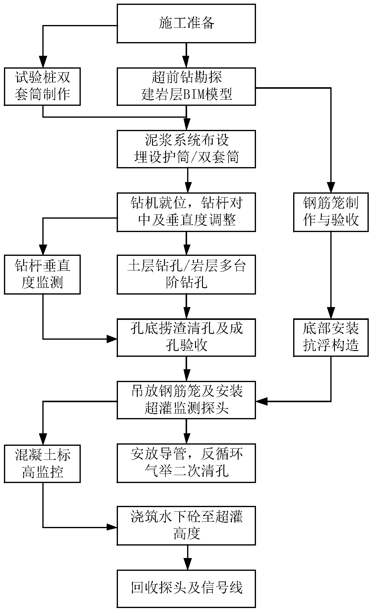
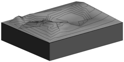
[0097] attached figure 1 As shown, the super-buried depth test pile construction method in the rock stratum of the present invention is a super-buried depth test pile construction method in the rock stratum. The method adopts a double sleeve structure, utilizes the outer sleeve to resist the soil pressure, and the inner sleeve as Concrete external formwork isolates the frictional resistance of the pile body of the empty pile, and realizes the accurate detection of the bearing capacity of the effective pile body before the excavation of the deep foundation pit; and then uses BIM technology to form a rock layer information model with the soil layer parameters obtained by multiple advanced drilling, and pre- Determine the length of the pile; then use the monitoring probe to automatically collect technical parameters in the process of underwater concrete pouring and perform data processing to dynamically monitor the height of the poured concrete, and use the preset limit value to r...


PUM


Abstract

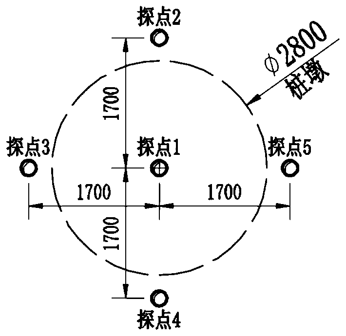
The invention discloses a construction method for a test pile with ultra-buried depth in a rock stratum, and belongs to the field of test pile construction. The technical problems that holes in a complex rock stratum are difficult to form, the underwater concrete ultra-pouring elevation cannot be accurately controlled, the static load detection operation conditions of the bottom of an ultra-deep foundation pit are limited, and the bearing detection is influenced by the control friction resistance for a cast-in-place pile are solved. According to the technical scheme, the method comprises the following steps that S1, construction preparation is carried out; S2, advanced drilling exploration is carried out, and a rock surface BIM model is established; S3, a protective cylinder is positionedand buried, and manufacturing and placing of double sleeves of the test pile are carried out; S4, a drilling machine is in place, and the centering and perpendicularity adjustment of a drill rod are carried out; S5, soil layer drilling, wall protection and rock stratum multi-stage step type drilling are carried out; S6, the perpendicularity of the drill rod is monitored by utilizing an internal and external double-control method; S7, a steel reinforcement cage is manufactured and an anti-floating structure is installed according to the step 2, the steel reinforcement cage is hoisted and placed, and an ultra-pouring monitoring probe is installed; S8, a guide pipe is placed, and secondary hole cleaning is carried out by adopting a gas lift reverse circulation method; and S9, underwater concrete pouring and ultra-pouring height monitoring are carried out.

Description

technical field [0001] The invention relates to the field of construction of test piles before excavation of building foundations, in particular to a construction method for super-buried deep test piles in rock formations. Background technique [0002] The test pile is a test device used before building construction. Its purpose is to check whether the bearing capacity and settlement of the pile foundation are consistent with the design, so as to ensure the quality of building construction. The test piles are generally carried out before the excavation of the building foundation pit or before the excavation reaches the level of the bottom of the trench. [0003] With the continuous increase of large-scale super high-rise and underground space construction projects, the foundation depth is also increasing, and the number of similar projects is increasing. Subsequently, the burial depth of pile tops has also been continuously increased, and engineering piles with a burial dep...

Claims


Application Information

Patent Timeline
Patent Type & Authority Applications(China)
IPC IPC(8): E02D5/34E02D13/04E02D13/08E02D5/66E02D33/00E21B11/00G06F30/13
CPCE02D5/34E02D5/66E02D13/04E02D13/08E02D33/00E21B11/00G06F30/13
Inventor 王伟董福永张串王安平葛群汪兆斌
Owner CHINA CONSTR EIGHTH ENG DIV
Learn More