Speed measurement magnetoelectric encoder based on multi-antipode magnetic steel and auxiliary stator winding

A technology of stator windings and encoders, applied in the field of magnetoelectric encoders, can solve the problems of high-frequency noise and inclusions, and achieve the effect of ensuring reliability and improving calculation accuracy

Active Publication Date: 2020-08-11
HARBIN UNIV OF SCI & TECH
View PDF23 Cites 10 Cited by
  • Summary
  • Abstract
  • Description
  • Claims
  • Application Information

AI Technical Summary

Problems solved by technology

[0004] However, the angle value signal of the magnetoelectric encoder is affected by the noise of the system power supply, and the angle value is mixed with high-frequency noise. For an encoder angle value calculation process, the angle value solution period is usually about 50 microseconds. The calculation of the speed needs to rely on the difference between the angle value of the current cycle and the angle value of the previous cycle divided by the time constant of the calculation cycle, because the time constant is in microsecond units, so when the speed is converted to revolutions per minute, it is equivalent to The difference value of the angle value is enlarged by 10 6 multiples, because the angle value signal is mixed with high-frequency noise, it is equivalent to synchronously amplifying the angle value noise by 10 during the speed calculation process. 6 multiples, which is extremely unfavorable for the speed loop control system. Aiming at this problem, the present invention proposes a speed-measuring magnetoelectric encoder based on multi-pair magnetic steel and auxiliary stator windings. In order to further improve the accuracy of angular velocity measurement, multiple pairs of The pole magnetic steel cooperates with the induction coil to obtain high-frequency induced voltage signals, and then performs data averaging processing to improve measurement accuracy

Method used


Image

  • Speed measurement magnetoelectric encoder based on multi-antipode magnetic steel and auxiliary stator winding
  • Speed measurement magnetoelectric encoder based on multi-antipode magnetic steel and auxiliary stator winding
  • Speed measurement magnetoelectric encoder based on multi-antipode magnetic steel and auxiliary stator winding

Examples


Embodiment Construction

[0026] In order to make the object, technical solution and advantages of the present invention clearer, the present invention is described below through specific embodiments shown in the accompanying drawings. It should be understood, however, that these descriptions are exemplary only and are not intended to limit the scope of the present invention. Also, in the following description, descriptions of well-known structures and techniques are omitted to avoid unnecessarily obscuring the concept of the present invention.

[0027] The specific structure and implementation mode of the present invention will be further described below in conjunction with the accompanying drawings.

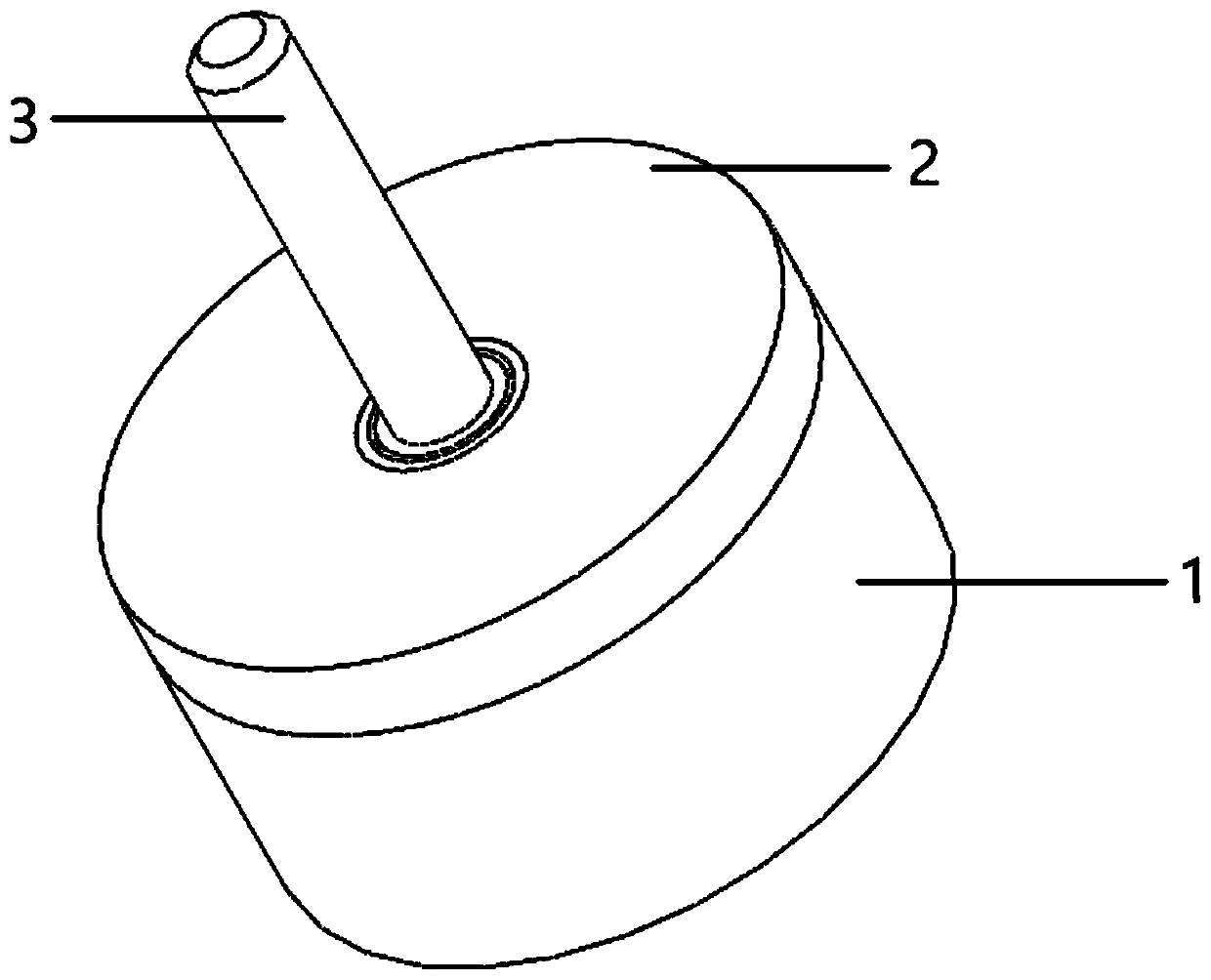
[0028] The structural composition of the present invention is as figure 1 , figure 2 , image 3 , Figure 4 .

[0029] A magnetoelectric encoder with an auxiliary stator coil at the end of the present invention comprises three parts: an encoder structure 1, an auxiliary stator coil structure 2, an...


PUM


Abstract

The invention discloses a magnetoelectric encoder with an end auxiliary stator coil. The auxiliary stator coil is cut by a magnetic field when multi-antipode magnetic steel rotates to generate voltage, the rotating speed of the current encoder is judged by reading a voltage peak value, and the rotating speed direction of the current encoder is obtained by an angle value signal differential value obtained by multi-antipode Hall calculation. The magnetoelectric encoder comprises an encoder structure, an auxiliary stator coil structure and a side shaft. The side shaft rotates, the multi-antipodemagnetic steel is driven to rotate to cut the auxiliary stator coil in a magnetic field, the voltage is generated, the higher the rotating speed of the rotor is, the higher the amplitude of the sine voltage obtained in the winding coil is, the voltage amplitude and the rotating speed are in a linear proportional relation, the rotating speed of the current encoder is judged by reading a voltage peak value, and the rotating speed direction of the current encoder is obtained through an angle value signal differential value obtained through multi-antipode Hall calculation.

Description

technical field [0001] The invention discloses a magnetoelectric encoder, in particular to a speed measuring magnetoelectric encoder based on multi-pair pole magnetic steel and auxiliary stator windings. Background technique [0002] The encoder is used to measure the angular position of the motor rotor and is the core component for motor control. It is widely used in high-tech fields such as mechanical engineering, robotics, aviation, and precision optical instruments, and plays a vital role in modern industry. Magnetic encoders have the advantages of simple structure, high temperature resistance, oil resistance, impact resistance, small size, and low cost, and have unique advantages in miniaturization and harsh environmental conditions. [0003] In the control system, the encoder communicates with the controller to transmit the angle value, which is used for the current loop control of the control system. The angle value is differentially calculated to obtain the current ...

Claims


Application Information

Patent Timeline
Patent Type & Authority Applications(China)
IPC IPC(8): G01P3/46G01B7/30
CPCG01P3/465G01B7/30G01B7/003
Inventor 王磊肖磊潘巍张永德
Owner HARBIN UNIV OF SCI & TECH
Why Eureka
Try Eureka