Steam turbine rotor digital twin construction method and monitoring system

A steam turbine rotor and construction method technology, applied in special data processing applications, design optimization/simulation, etc., can solve problems such as harsh working conditions, inability to effectively grasp the state of steam turbine rotors, and large economic losses, so as to improve reliability and safety , To ensure the effect of long-term safe operation

Active Publication Date: 2020-08-11
SHANGHAI POWER EQUIP RES INST +2
View PDF8 Cites 4 Cited by
  • Summary
  • Abstract
  • Description
  • Claims
  • Application Information

AI Technical Summary

Problems solved by technology

[0002] The high-pressure rotor, medium-pressure rotor and low-pressure rotor of the steam turbine are the core components of the steam turbine. The steam turbine rotor rotates at high speed and the working conditions are harsh. Once a problem occurs, the downtime will be long and the economic loss will be huge
Since the rotor is in a high-speed rotating state during the operation of the steam turbine, online measuring points cannot be installed. The traditional technology mainly detects the state of the rotor indirectly by installing measuring points on the inner cylinder wall, and faces the technical problem of being unable to effectively grasp the state of the steam turbine rotor.

Method used


Image

  • Steam turbine rotor digital twin construction method and monitoring system
  • Steam turbine rotor digital twin construction method and monitoring system
  • Steam turbine rotor digital twin construction method and monitoring system

Examples


Embodiment Construction

[0023] Below in conjunction with specific embodiment, further illustrate the present invention. It should be understood that these examples are only used to illustrate the present invention and are not intended to limit the scope of the present invention. In addition, it should be understood that after reading the teachings of the present invention, those skilled in the art can make various changes or modifications to the present invention, and these equivalent forms also fall within the scope defined by the appended claims of the present application.

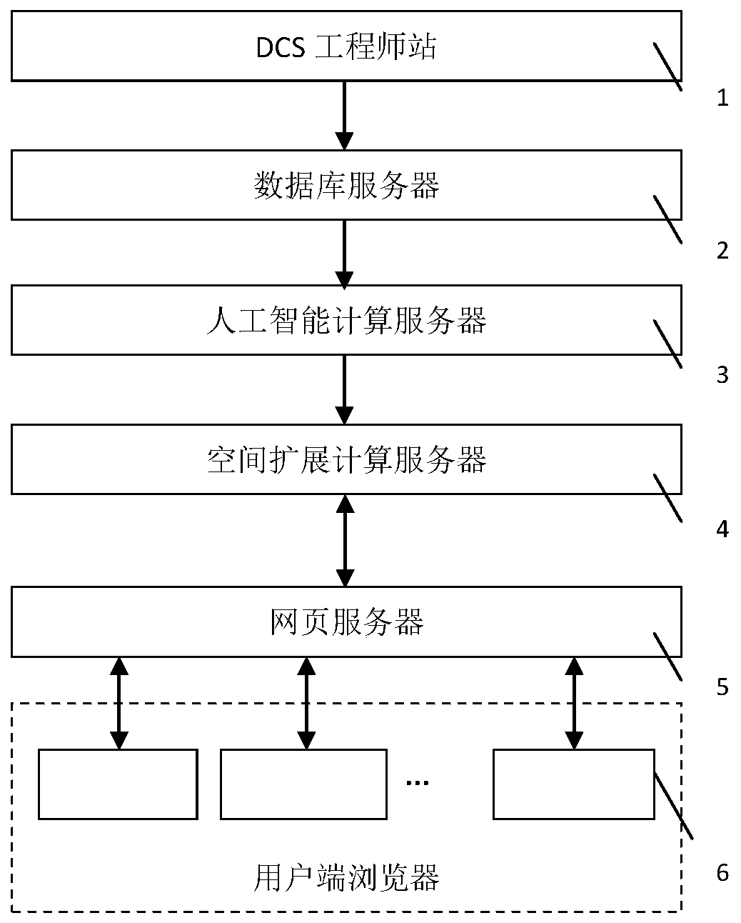
[0024] Such as figure 1 As shown, the block diagram of the steam turbine rotor digital twin monitoring system of the present invention, the steam turbine rotor digital twin monitoring system of the present invention consists of a steam turbine rotor database server 1, an artificial intelligence computing server 2, a space expansion computing server 3, a web server and a client browser 4. The steam turbine rotor database server...


PUM


Abstract

The invention provides a steam turbine rotor digital twin construction method. Another technical scheme of the invention is to provide a steam turbine rotor digital twin monitoring system. The steam turbine rotor digital twin construction method adopts a digital twin technology, and comprises the steps of: firstly, establishing a two-dimensional rotor twin model, establishing a digital twin consistent with entity characteristics of a steam turbine rotor through adopting a node expansion technology, and mastering the state of the steam turbine rotor comprehensively, thereby achieving the technical effects of improving the reliability and safety of the steam turbine rotor and ensuring long-period safe operation of the steam turbine. According to the steam turbine rotor digital twin construction method and the steam turbine rotor digital twin monitoring system provided by the invention, an artificial intelligence and space expansion cloud chart construction technology is adopted, reconstruction of the two-dimensional digital twin of the steam turbine rotor, three-dimensional expansion of the model and rapid display and monitoring of a temperature field, a stress field and a displacement field are achieved online, and monitoring of the states of the steam turbine rotor is achieved.

Description

technical field [0001] The invention relates to a method for constructing a steam turbine rotor digital twin and a monitoring system, and belongs to the technical field of steam turbines. Background technique [0002] The high-pressure rotor, medium-pressure rotor and low-pressure rotor of the steam turbine are the core components of the steam turbine. The steam turbine rotor rotates at high speed and the working conditions are harsh. Once a problem occurs, the downtime will be long and the economic loss will be huge. Since the rotor is in a high-speed rotating state during the operation of the steam turbine, online measuring points cannot be installed. The traditional technology mainly detects the state of the rotor indirectly by installing measuring points on the inner cylinder wall, and faces the technical problem of being unable to effectively grasp the state of the steam turbine rotor. Contents of the invention [0003] The purpose of the present invention is to estab...

Claims


Application Information

Patent Timeline
Patent Type & Authority Applications(China)
IPC IPC(8): G06F30/23G06F30/27
CPCG06F30/23G06F30/27Y02E60/00
Inventor 汪勇吴岩郑耀东郭荣杨天明高怀玉张铎刘菊菲高明张玉江满玉军朱宪磊邓志成曹振东张振文范佳卿
Owner SHANGHAI POWER EQUIP RES INST
Why Eureka
Try Eureka