Antenna

A technology for antennas and reflectors, which is applied in the structural connection of antennas, antenna grounding switches, antenna supports/mounting devices, etc., can solve the problems of many fastening points and complex assembly, and achieve the reduction of solder joints, simple assembly structure, and low The effect of process requirements

Pending Publication Date: 2020-08-11
COMBA TELECOM TECH (GUANGZHOU) CO LTD +1
View PDF0 Cites 6 Cited by
  • Summary
  • Abstract
  • Description
  • Claims
  • Application Information

AI Technical Summary

Problems solved by technology

This assembly and connection method has the problems of complex assembly and many fastening points

Method used


Image

  • Antenna
  • Antenna
  • Antenna

Examples


Embodiment Construction

[0031] Embodiments of the present invention are described in detail below, examples of which are shown in the drawings, wherein the same or similar reference numerals designate the same or similar elements or elements having the same or similar functions throughout. The embodiments described below by referring to the figures are exemplary only for explaining the present invention and should not be construed as limiting the present invention.

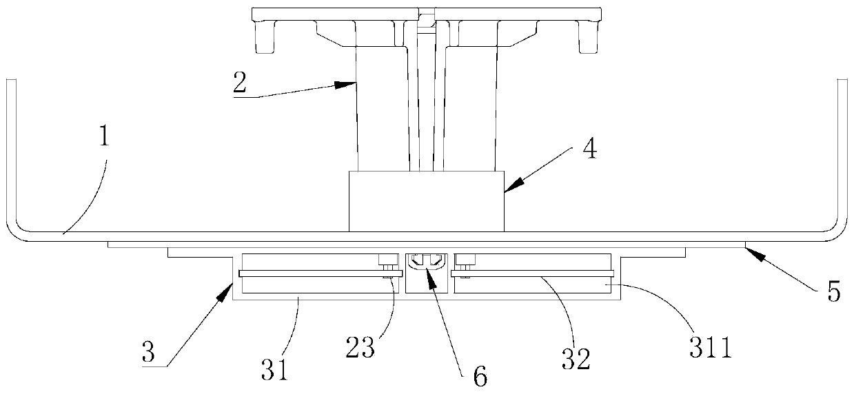
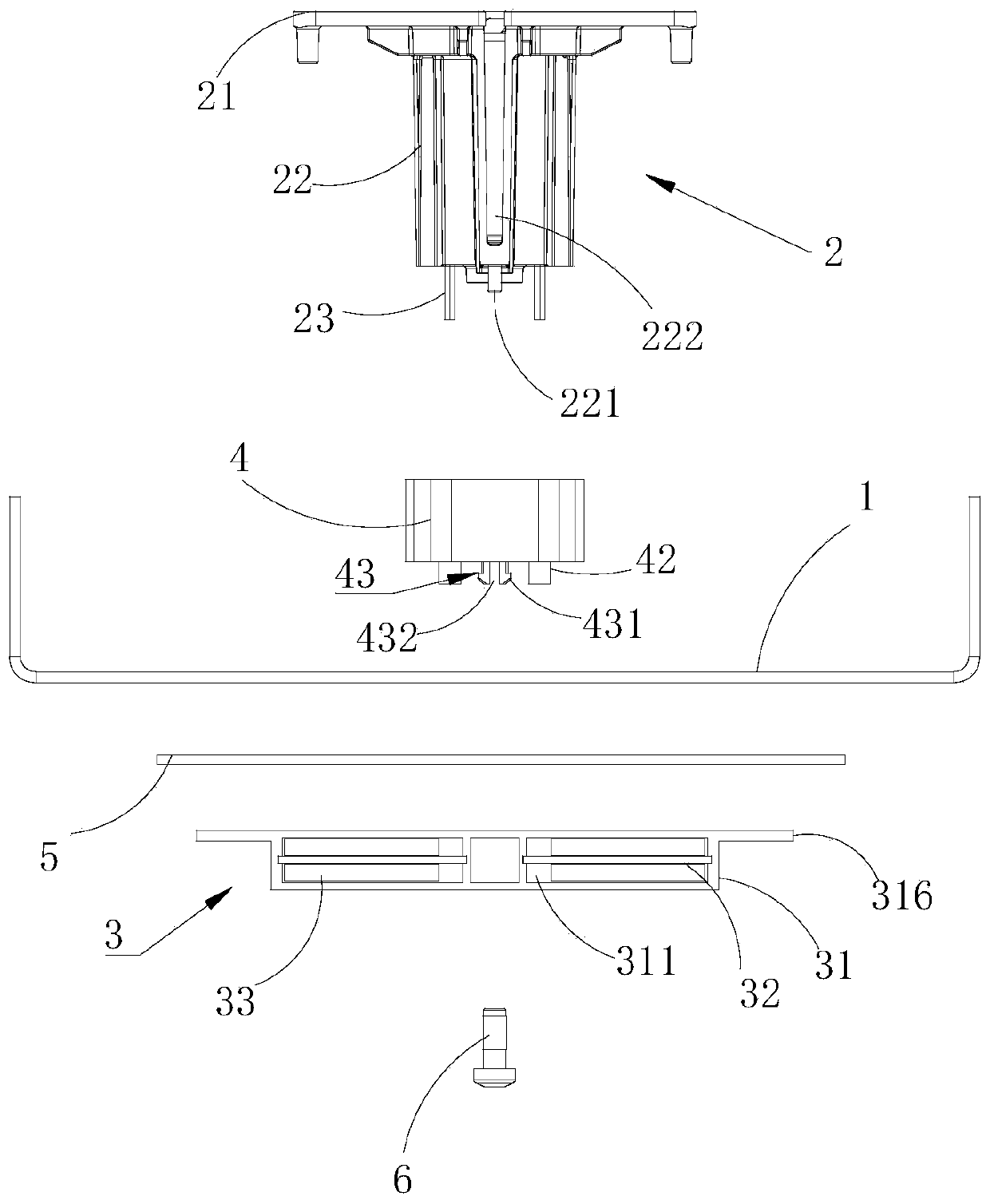
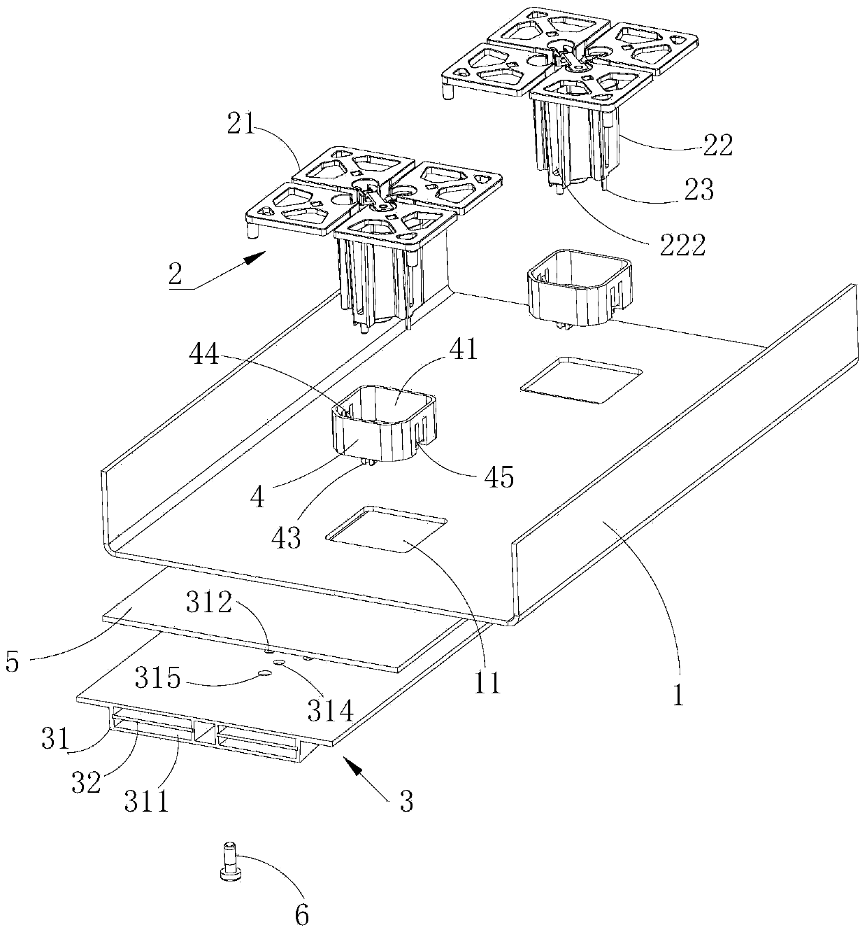
[0032] Such as Figure 1 to Figure 4 As shown, the present invention provides an antenna, including a reflector 1, a radiation unit 2 and a phase shifter 3, the radiation unit 2 and the phase shifter 3 are separately arranged on both sides of the reflector 1, and the reflector 1 are respectively insulated and connected to the radiation unit 2 and the phase shifter 3, and the radiation unit 2 includes a radiation arm 21, a balun 22 for supporting the radiation arm 21, and a feed sheet 23 for feeding the radiation arm 21 , the phase shift...


PUM


Abstract

The invention provides an antenna. The key points of the technical scheme are that the antenna comprises a reflecting plate, and a radiation unit and a phase shifter which are arranged at two sides ofthe reflection plate; the reflecting plate is respectively connected with the radiation unit and the phase shifter in an insulating manner, the radiation unit comprises a feed sheet for feeding the radiation arm, the phase shifter comprises a cavity and a phase shifting circuit arranged in the cavity, and the feed sheet penetrates through the reflecting plate, penetrates into the cavity and is electrically connected with the phase shifting circuit. The radiation unit, the reflecting plate and the phase shifter are arranged in a stacked manner; the feed sheet of the radiation unit extends intothe phase shifter to be connected with the phase shift circuit, and an external feed cable is not needed, so that the assembly structure of the antenna is simpler, welding spots are reduced, hidden dangers caused by the welding spot problem are avoided, the feed cable is reduced, the dielectric loss is also avoided, and the antenna gain is improved.

Description

technical field [0001] The invention relates to the field of mobile communication, in particular to an antenna. Background technique [0002] The radiating element and the phase shifter are the two core components of the electronically adjustable antenna. In the conventional design, the radiating unit and the phase shifter are often designed separately. After the design is completed, the two are electrically connected through PCB or coaxial cable, so as to ensure electromagnetic wave radiation and control electrical scanning. This assembly and connection method has the problems of complicated assembly and many fastening points. Contents of the invention [0003] The object of the present invention is to provide an antenna with simple assembly structure. [0004] In order to achieve the above object, the present invention provides the following technical solutions: [0005] An antenna, comprising a reflector and a radiation unit and a phase shifter arranged on both sides...

Claims


Application Information

Patent Timeline
Patent Type & Authority Applications(China)
IPC IPC(8): H01Q1/12H01Q1/36H01Q1/50H01Q19/10H01Q3/34
CPCH01Q1/12H01Q1/36H01Q1/50H01Q3/34H01Q19/106
Inventor 贾飞飞李明超杨仲凯苏国生王强薛泉
Owner COMBA TELECOM TECH (GUANGZHOU) CO LTD
Why Eureka
Try Eureka