Natural gas filter

A natural gas and filter technology, applied in the direction of dispersed particle filtration, gas fuel, chemical instruments and methods, etc., can solve the problems of gas outlet pipe fittings deposition, pressure regulating valve damage, complicated operation, etc., achieve simple cleaning methods and improve cleanliness , Improve the effect of cleanliness

Inactive Publication Date: 2020-08-14
杭州昕华信息科技有限公司
View PDF5 Cites 1 Cited by
  • Summary
  • Abstract
  • Description
  • Claims
  • Application Information

AI Technical Summary

Problems solved by technology

[0003] Because when the filter device is filtering natural gas, a large amount of solid impurities will accumulate on the outer wall of the filter element, so it is necessary to take out the filter element after a period of use, and then clean or replace the filter element. Only after the cover of the filter is opened can the filter element be taken out. This process is complicated, time-consuming and labor-intensive; and when the filter element is taken out, there will still be a small amount of impurities on the outer wall that will fall from the filter element to the outlet pipe due to vibration and other factors. , the falling impurities will move to the pressure regulating valve and other equipment with the re-input natural gas in the later stage, which will cause damage to the pressure regulating valve; Chinese patent CN104289045B discloses an anti-clogging natural gas filter, which intercepts dust by setting Although it has a good dust-proof effect, in the actual use process, because the dust is small in size and light in weight, a large amount of dust will still fall down when it is taken out, which will still cause accidents. A small amount of dust is deposited in the air pipe fittings, which will still cause damage to the downstream equipment during use, so it is still necessary to use effective equipment to prevent dust during disassembly

Method used


Image

  • Natural gas filter
  • Natural gas filter
  • Natural gas filter

Examples


Embodiment Construction

[0031] In order to enable those skilled in the art to better understand the solutions of the present invention, the technical solutions in the embodiments of the present invention will be clearly and completely described below in conjunction with the drawings in the embodiments of the present invention.

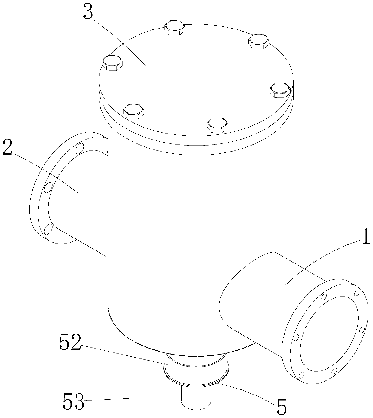
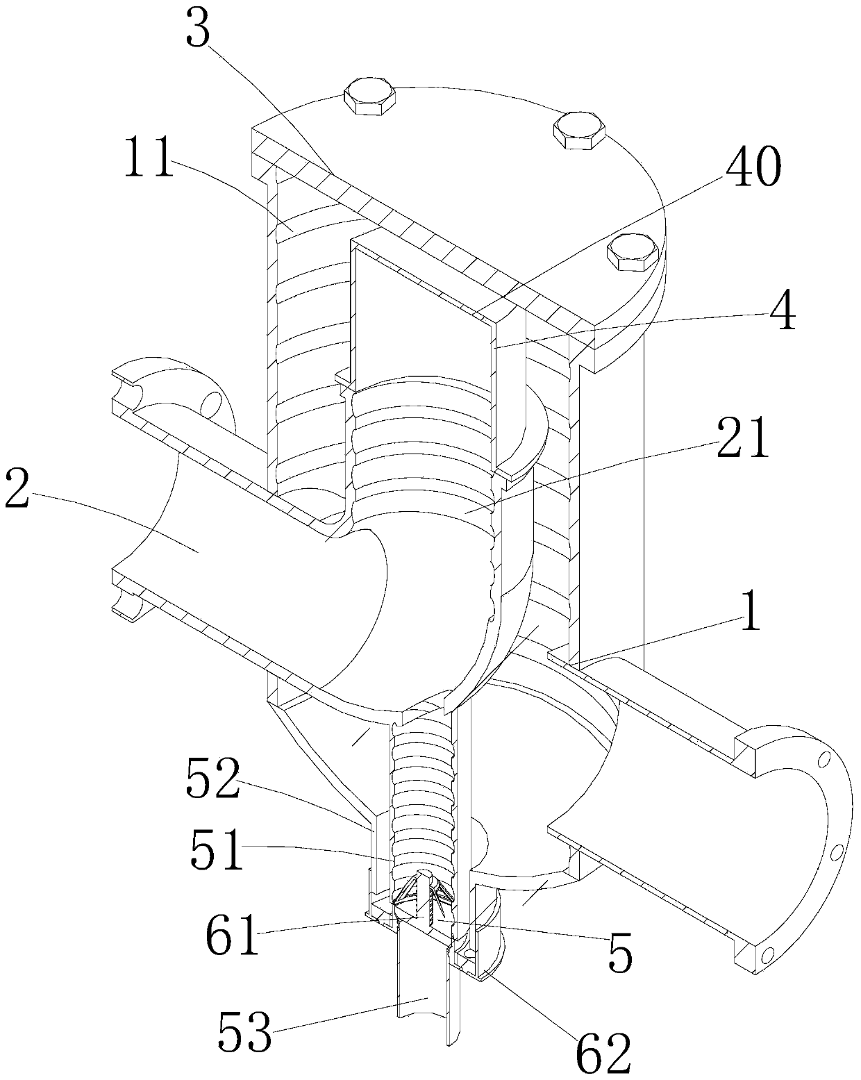
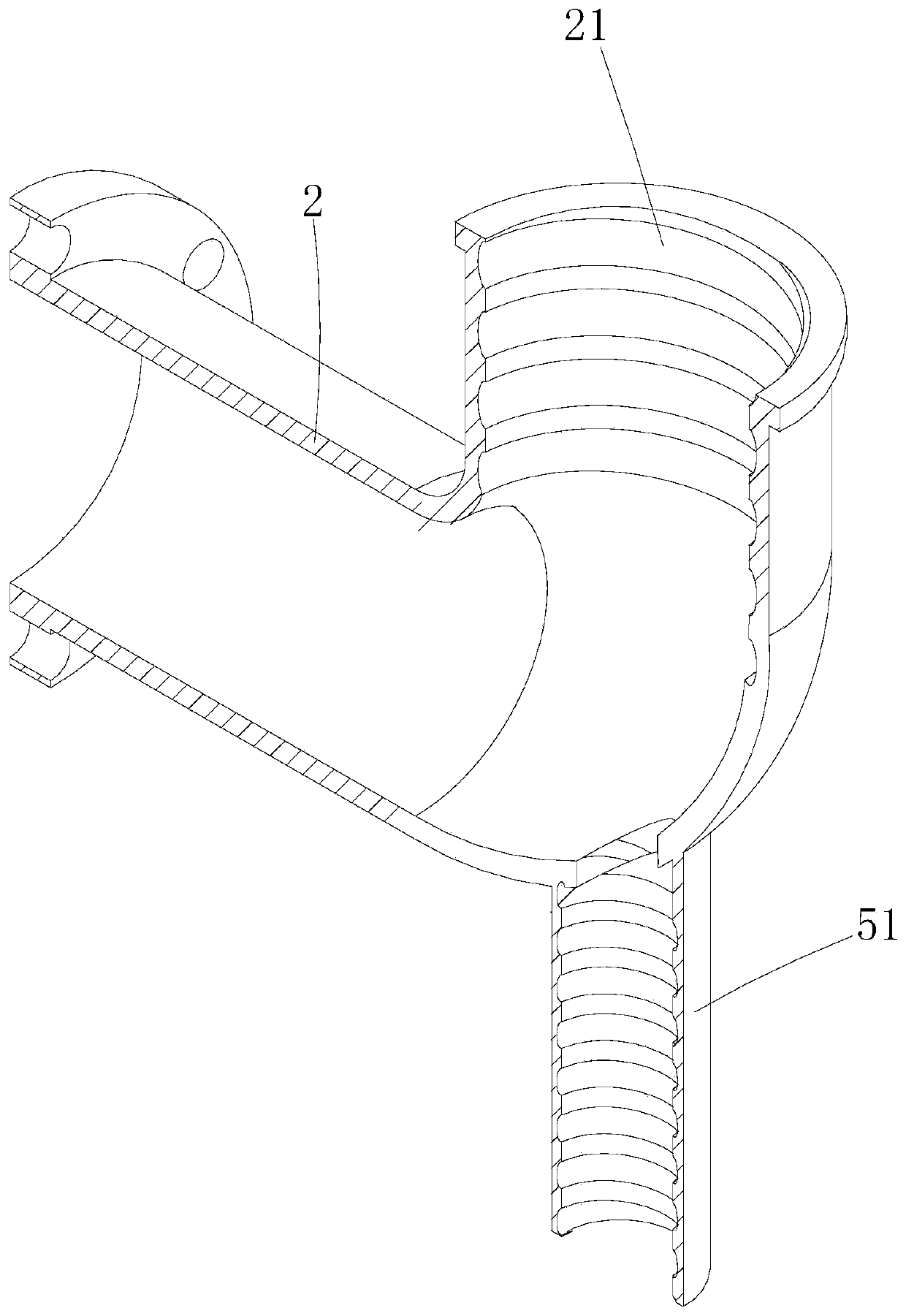
[0032] Such as Figure 1-9 As shown, a natural gas filter includes an air intake pipe fitting 1, an air outlet pipe fitting 2, a cover plate 3, a filter structure 4 and a sewage discharge structure 5, the air intake pipe fitting 1 is an L-shaped metal pipe, and unfiltered natural gas flows from Into the middle of the air intake pipe 1, a second helical groove 11 is provided on the inner wall of the air intake pipe 1, and the second helical groove 11 is a threaded groove formed on the air intake pipe 1. ; The outlet pipe part 3 is also a metal pipe, and the outlet pipe part 2 is also an L-shaped metal pipe. The first spiral groove 21 is provided on the top, and the first spir...


PUM


Abstract

The invention discloses a natural gas filter which comprises an L-shaped gas inlet pipe fitting, and a pollution discharge structure. Natural gas containing impurities enters the natural gas filter through the gas inlet pipe fitting. The pollution discharge structure is used for blowing out air to a filter element from inside to outside so as to blow off solid impurities attached to the outer wallof the filter element, and meanwhile, the solid impurities are blown out from the bottom of the gas inlet pipe fitting. The air is fed into the filter element, the solid impurities adhered to the outer wall of the filter element are blown to float, and the solid impurities on the outer wall of the filter element can be effectively blown out in the process, so that filter holes are kept unblocked,the time for taking out the filter element for cleaning is prolonged, the working procedure required by cleaning is saved, and the filtering effect of the filter element on the natural gas can also be improved.

Description

technical field [0001] The invention belongs to the technical field of gas filters, in particular to a natural gas filter. Background technique [0002] As a new energy dye, natural gas is mainly composed of methane, and also contains a small amount of ethane, propane and butane. After burning, the dye will produce carbon dioxide and water, but natural gas contains a small amount of solid impurities and moisture. In the process of natural gas transmission, natural gas needs to be filtered to remove impurities in natural gas, so as to improve the combustion efficiency of natural gas, and also to prevent solid impurities from entering the combustion device, causing blockage or damage to the device. [0003] Because when the filter device is filtering natural gas, a large amount of solid impurities will accumulate on the outer wall of the filter element, so it is necessary to take out the filter element after a period of use, and then clean or replace the filter element. Only ...

Claims


Application Information

Patent Timeline
Patent Type & Authority Applications(China)
IPC IPC(8): B01D46/00C10L3/10
CPCC10L3/101B01D46/70
Inventor 佟勇华
Owner 杭州昕华信息科技有限公司
Why Eureka
Try Eureka