Veneer longitudinal glue splicing process and veneer longitudinal glue splicing machine

A gluing machine and veneer technology, which is applied in the jointing of wooden veneers, manufacturing tools, wood processing equipment, etc., can solve the problem of increasing the cost of consumables, transportation costs, space costs, and the horizontal length of the vertical gluing machine Long, consumables and increased floor space, to achieve the effect of reducing the weight of the whole machine equipment, compact structure, reducing the cost of consumables and transportation costs

Pending Publication Date: 2020-08-14
刘小志
View PDF2 Cites 5 Cited by
  • Summary
  • Abstract
  • Description
  • Claims
  • Application Information

AI Technical Summary

Problems solved by technology

However, the workflow disclosed in CN110480767A and CN110466012A is that after the tail of the veneer is punched, the teeth are then spliced. Due to the limitation of the veneer length specifications currently on the market, it is generally between 125 centimeters and 129 centimeters, and 127 centimeters is the most suitable. Commonly, the distance between the tooth cutting device and the tooth connection device is set to be more than 125 cm, which results in a long horizontal length of the longitudinal gluing machine, and the moving distance of the veneer after the tail is punched and before the tooth connection is too long. The displacement error in the process also increases correspondingly, which reduces the precis

Method used


Image

  • Veneer longitudinal glue splicing process and veneer longitudinal glue splicing machine

Examples


Example Embodiment

[0025] In order to make the objectives, technical solutions, and advantages of the invention clearer, a veneer longitudinal glue-bonding machine will be described in further detail below in conjunction with the drawings and embodiments. It should be understood that the specific embodiments described here are only used to explain the invention, but not to limit the invention.

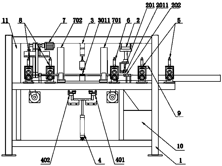
[0026] Such as figure 1 As shown, a veneer longitudinal glue assembly machine includes a main frame 1, a tooth cutting device 2, a tooth cutting transfer device 5, a tooth connection transfer device 6, a board exit transfer device 8, a splint moving device 7, a glue making device 4, Tooth connection device 3, fixed-length cutting device 11, photoelectric switch 9, controller 10, the main frame 1 is provided with a tooth cutting conveyor 5, a tooth cutting device 2, and a tooth connecting conveyor 6 in sequence from one side to the other side , The first splint platform 701, the first glue-dispensing tooth ...


PUM

PropertyMeasurementUnit
Tooth lengthaaaaaaaaaa

Abstract

The invention discloses a veneer longitudinal glue splicing process and a veneer longitudinal glue splicing machine. The veneer longitudinal glue splicing machine comprises a main frame, a tooth cutting device, a tooth cutting conveying device, a tooth joint conveying device, a plate discharging conveying device, a clamping plate moving device, a gluing device, a tooth joint device, a fixed-lengthcutting device, an optoelectronic switch and a controller. The horizontal spacing distance between the tooth joint device and the tooth cutting device is limited to range from 45 cm to 90 cm, the displacement distance of a veneer after tooth beating and before splicing is reduced, errors are reduced, and the tooth joint precision is improved; a good tooth joint effect can be achieved for a wood plate with the tooth length of 3 cm after tooth combing, consumables of the tooth joint end of the veneer are reduced, and the utilization rate of the veneer is increased; the occupied space of complete equipment is reduced, the weight of the complete equipment is reduced, and the consumable cost and transportation cost of equipment products are reduced; and the application range is wide, and various veneers with different lengths, veneers with different thicknesses and veneers adhered with impurities can be longitudinally spliced by a single glue splicing machine.

Description

technical field [0001] The invention belongs to wood processing machinery, in particular to the technical field of veneer splicing in wood production, and in particular to a tooth joint device for longitudinal glue splicing of thick veneers. Background technique [0002] In the past two years, several tooth joint devices have appeared for longitudinal / vertical splicing equipment of medium plates. For example, the technical solutions disclosed in patent documents such as CN110480767A and CN110466012A provide the market with numerous technical solutions for veneer longitudinal gluing. However, the workflow disclosed in CN110480767A and CN110466012A is that after the tail of the veneer is punched, the teeth are then spliced. Due to the limitation of the veneer length specifications currently on the market, it is generally between 125 centimeters and 129 centimeters, and 127 centimeters is the most suitable. Commonly, the distance between the tooth cutting device and the tooth ...

Claims


Application Information

Patent Timeline
IPC IPC(8): B27D1/10
CPCB27D1/10
Inventor 刘小志
Owner 刘小志
Why Eureka
Try Eureka