Take-off and landing device for ultra-light small unmanned aerial vehicle

An unmanned aerial vehicle, small-scale technology, applied in the direction of unmanned aircraft, aircraft, transportation and packaging, etc., to achieve the effect of convenient assembly, reducing the use of connecting parts and connecting screws, and convenient processing

Pending Publication Date: 2020-08-14
NORTHWESTERN POLYTECHNICAL UNIV
View PDF0 Cites 2 Cited by
  • Summary
  • Abstract
  • Description
  • Claims
  • Application Information

AI Technical Summary

Problems solved by technology

At present, there is no related design that can meet the above requirements at the same time.

Method used


Image

  • Take-off and landing device for ultra-light small unmanned aerial vehicle
  • Take-off and landing device for ultra-light small unmanned aerial vehicle
  • Take-off and landing device for ultra-light small unmanned aerial vehicle

Examples


Embodiment Construction

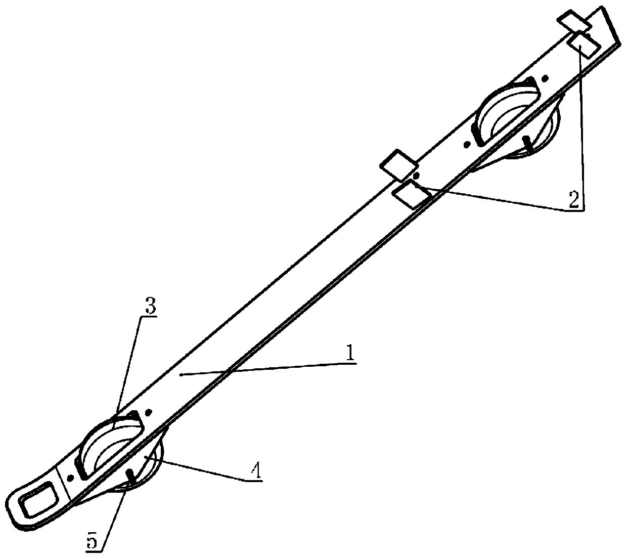
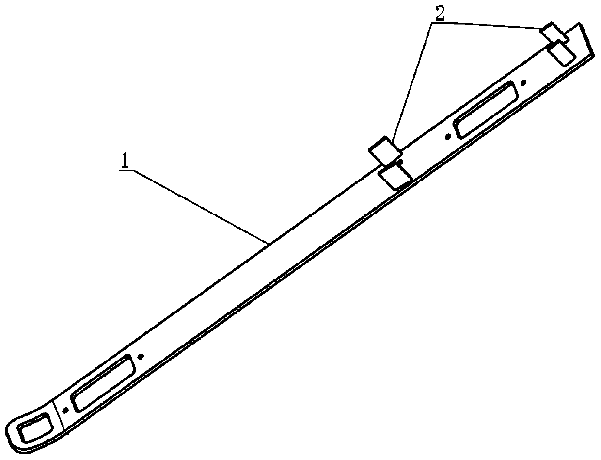
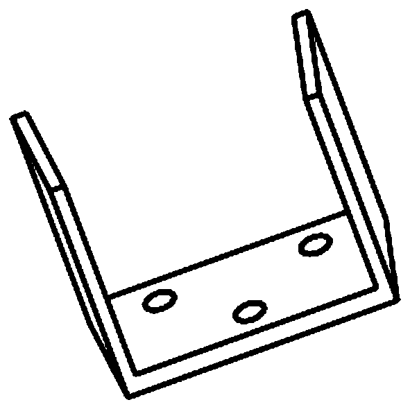
[0028] In order to enable the aircraft to withstand greater impact loads and reduce damage to the aircraft landing gear and the fuselage, the conventional wheeled landing gear is changed into a skid landing gear in the present invention, and the skid structure landing gear will play a role when the aircraft lands. Buffer function, absorbing the energy brought by the vertical velocity during landing, bearing the impact load when the aircraft lands, and reducing the overload caused by landing impact. The main structure is as follows: figure 1 shown. According to the size and position of the vertical tail of the aircraft, two pairs of 4 vertical tail fixing slots and 2 square tire limiting holes are respectively opened on the skid plate. The two vertical tail fixing brackets are fixedly connected to the vertical tail of the aircraft through the card slot; the two square tire limit holes are limit installation holes corresponding to the positions of the corresponding vehicle fixin...


PUM


Abstract

The invention provides a take-off and landing device for an ultra-light small unmanned aerial vehicle. The take-off and landing device is composed of a skid plate, a vertical tail fixing piece and a pulley mechanism. According to a size and a position of the airplane vertical tail, two pairs of vertical tail fixing piece clamping grooves and two square tire limiting holes are arranged in the skidplate. The two vertical tail fixing frames penetrate through the clamping grooves to be fixedly connected with the airplane vertical tail; and the two square tire limiting holes are limiting mountingholes corresponding to the positions of corresponding vehicle-mounted fixing devices so that a undercarriage not only can automatically take off and land in a sliding manner, but also can take off ina vehicle-mounted manner and land in a sliding manner when a runway environment is poor. The device has good compression resistance, tensile strength and torsion resistance performance, a plate structure of a main body greatly increases a contact area when the undercarriage lands so that an impact load caused by the dead weight of an aircraft at the moment of landing is dispersed, an impact load resistance capability is improved, and damage to an airplane during landing is reduced to the minimum.

Description

technical field [0001] The invention relates to the field of unmanned aerial vehicle landing gear structure design, in particular to a landing gear device for ultra-light and small unmanned aerial vehicles. Background technique [0002] The landing gear is an accessory device located in the lower part of the aircraft to support the aircraft and move on the ground during takeoff and landing or ground taxiing. It is the only part that supports the entire aircraft. In the process of designing the landing gear structure of unmanned aerial vehicles, on the one hand, it is necessary to take into account the integrity of the landing gear function and its stringent weight requirements. The rigidity and strength of the landing gear must be able to bear the huge impact brought by the aircraft when it lands, and the overall structure can withstand the impact load when the aircraft lands and the ground. [0003] A certain type of ultra-light small unmanned aerial vehicle has multiple w...

Claims


Application Information

Patent Timeline
Patent Type & Authority Applications(China)
IPC IPC(8): B64C25/36
CPCB64C25/36B64U10/00
Inventor 刘红军周洲黎鹏沈冰周栋王正平
Owner NORTHWESTERN POLYTECHNICAL UNIV
Why Eureka
Try Eureka