Novel corrugated web steel-concrete continuous beam bridge

A corrugated web and corrugated steel web technology, applied in bridges, buildings, etc., can solve the problems of uneconomical material consumption, large amount of concrete pouring, complex local stress, etc. The effect of bending stiffness

Pending Publication Date: 2020-08-14
甘肃省交通规划勘察设计院股份有限公司
View PDF0 Cites 0 Cited by
  • Summary
  • Abstract
  • Description
  • Claims
  • Application Information

AI Technical Summary

Problems solved by technology

Traditional corrugated steel web composite box girders are mostly closed sections, and the temperature difference between the inside and outside of the box girder is large, and the temperature gradient difference between inside and outside is likely to generate additional stress on the concrete roof and floor, which will have an adverse effect on the structure; when using a single box or single room or For a single-box multi-chamber structure, according to the shear lag effect theory, the actual stress borne by some roof and bottom plates is relatively small, which greatly exceeds the effective distribution width range, resulting in excessive cross-sectional dimensions and uneconomical material consumption; corrugated steel web composite box girder settings Some concrete mid-diaphragm beams are used to limit distortion and increase the torsional rigidity. However, for sections with larger widths, concrete mid-beams are used, and the amount of concrete pouring is large, resulting in complex local stresses.

Method used


Image

  • Novel corrugated web steel-concrete continuous beam bridge
  • Novel corrugated web steel-concrete continuous beam bridge
  • Novel corrugated web steel-concrete continuous beam bridge

Examples


Embodiment 1

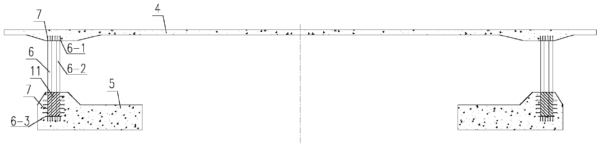
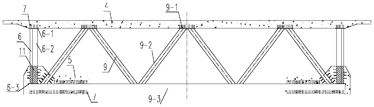
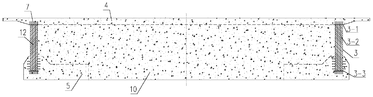
[0041] Please refer to Figure 1-7 ,in, figure 1 It is a schematic cross-section of the steel-concrete continuous girder bridge with corrugated webs in Example 1 of the present invention figure 1 ; figure 2 It is a schematic cross-section of the steel-concrete continuous girder bridge with corrugated webs in Example 1 of the present invention figure 2 ; image 3 It is a schematic cross-section of the steel-concrete continuous girder bridge with corrugated webs in Example 1 of the present invention image 3 ; Figure 4 It is a schematic diagram of the floor shear stud-through reinforcement combination of the corrugated web steel-concrete continuous girder bridge according to Embodiment 1 of the present invention; Figure 5 It is a schematic diagram of the façade of the corrugated web steel-concrete continuous beam bridge of Embodiment 1 of the present invention; Figure 6 It is a planar projection schematic diagram of the corrugated web steel-concrete continuous girder br...

Embodiment 2

[0065] In order to make the above objects, features and advantages of the present invention more comprehensible, the present invention will be further described in detail below in conjunction with the accompanying drawings and specific embodiments.

[0066] Please refer to Figure 8-14 ,in, Figure 8 It is the schematic cross-section of the steel-concrete continuous girder bridge with corrugated webs in Example 2 of the present invention figure 1 ; Figure 9 It is the schematic cross-section of the steel-concrete continuous girder bridge with corrugated webs in Example 2 of the present invention figure 2 ; Figure 10 It is the schematic cross-section of the steel-concrete continuous girder bridge with corrugated webs in Example 2 of the present invention image 3 ; Figure 11 It is a schematic diagram of the floor shear stud-through reinforcement combination of the corrugated web steel-concrete continuous girder bridge according to Embodiment 2 of the present invention; ...


PUM


Abstract

The invention relates to a novel corrugated web steel-concrete continuous beam bridge. The novel corrugated web steel-concrete continuous beam bridge comprises a fulcrum first-type corrugated steel web combined box girder, a variable-height section second-type corrugated steel web combined box girder and an equal-height section third-type corrugated steel web combined box girder. The corrugated steel web combined box girder comprises a concrete top plate, a concrete bottom plate, a corrugated web combined steel box connected with the concrete top plate and the bottom plate through shear nails,a fulcrum concrete cross beam and a truss type steel cross beam, wherein the fulcrum concrete cross beam and the truss type steel cross beam are arranged in the corrugated steel web combined beam. The corrugated web combined steel box and the steel cross beam are connected with the concrete top plate and the bottom plate through the shear nails or shear nail-penetrating steel bar combinations. The novel corrugated web steel-concrete continuous beam bridge is constructed through a hanging basket, a construction period is short, a stress is clear, the structure is light, a design concept of green construction and a light large span is met, social and economic benefits are remarkable, and the novel corrugated web steel-concrete continuous beam bridge has important significance in promoting application of steel structure bridges in China.

Description

technical field [0001] The invention belongs to the technical field of bridge engineering, and in particular relates to a novel corrugated web steel-concrete continuous girder bridge. Background technique [0002] The traditional continuous girder bridge mostly adopts the prestressed concrete box girder main girder structure. The concrete box girder bridge has a large self-weight, the web is made of thick concrete, and the amount of steel reinforcement is huge. The size of the substructure is often large, and the overall cost is high; concrete The box girder structure adopts the longitudinal, horizontal and vertical three-dimensional prestressing system, and the efficiency of prestressing introduction is low; the construction speed of concrete box girder sections is slow, and due to the large self-weight, more sections are required, and the construction period is increased ; Prestressed concrete box girders are prone to longitudinal cracks in the roof and oblique cracks in t...

Claims


Application Information

Patent Timeline
Patent Type & Authority Applications(China)
IPC IPC(8): E01D12/00
CPCE01D12/00
Inventor 李光明武维宏樊江华旭东张春明陈辅一
Owner 甘肃省交通规划勘察设计院股份有限公司
Why Eureka
Try Eureka