Fan coil pipe heat exchanger

A fan coil and heat exchanger technology, applied in indirect heat exchangers, heat exchanger shells, heat exchanger types, etc., can solve the problems of noise generated by fan devices, affecting heat exchange efficiency, and easy to generate water, etc. Achieve the effect of preventing clogging, speeding up heat exchange efficiency and improving filtration effect

Inactive Publication Date: 2020-08-14
滁州市胜威电力信息咨询有限公司
View PDF0 Cites 0 Cited by
  • Summary
  • Abstract
  • Description
  • Claims
  • Application Information

AI Technical Summary

Problems solved by technology

[0004] In order to make up for the shortcomings of the existing technology and solve the low heat exchange efficiency, the fan unit of the fan coil heat exchanger will produce noise when it is working, and the heat exchanger will produce condensation water when it is working, and when the condensation water accumulates be

Method used


Image

  • Fan coil pipe heat exchanger
  • Fan coil pipe heat exchanger
  • Fan coil pipe heat exchanger

Examples


Example Embodiment

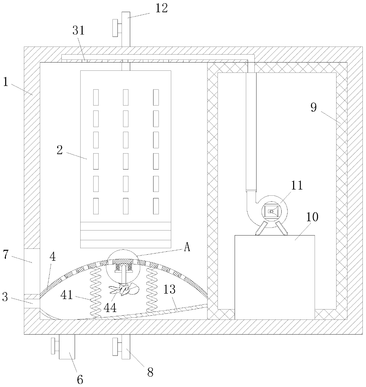
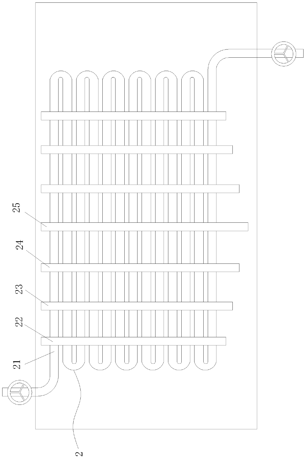
[0029] As a specific embodiment of the present invention, the coil pipe 21 runs through the first fin 22, the second fin 23, the third fin 24 and the fourth fin 25 to form a ring-shaped structure, and the first fin The tops of the sheet 22, the second fin 23, the third fin 24 and the fourth fin 25 are at the same level, and the first fin 22, the second fin 23, the third fin 24 and the fourth fin 25 The height of the bottom of the bottom from the ground gradually decreases; when working, because the first fin 22, the second fin 23, the third fin 24 and the fourth fin 25 are arranged in layers according to the height of the bottom from the ground, the condensation The dew will gradually flow from the first fin 22 which is higher at the bottom to the fourth fin 25 which is lower at the bottom step by step, and then slowly flow into the bottom of the device, so that the flow rate of dew can be delayed and water accumulation can be avoided Sudden excessive flooding of the heat exch...


PUM


Abstract

The invention belongs to the technical field of heat exchangers, and particularly discloses a fan coil pipe heat exchanger. The fan coil pipe heat exchanger comprises a shell, a heat exchanger body, afiltering disc, a drainage pipe, a coil pipe water outlet pipe, a sound absorbing pad, a fan body and a controller. The heat exchanger body is arranged in the shell; a coil pipe water inlet pipe is arranged at the upper end of the heat exchanger body; the coil pipe water outlet pipe is arranged at the lower end of the heat exchanger body; and the filtering disc is arranged above the coil pipe water outlet pipe. According to the fan coil pipe heat exchanger, a plurality of rows of coil pipes penetrate through a plurality of fin structures at different height side by side; the heat exchange efficiency can be improved through the arrangement of a plurality of rows of the coil pipes; through the fins which are arranged at different height, condensate water can gradually flow from a first finwith higher bottom end to a fourth fin with lower bottom end stage by stage and then flow into a water accumulation tank, so that the flow rate is slowed down; the damage to the heat exchanger body caused by flooding the same with excessive accumulation water is avoided; impurities in the condensate water can be filtered by the filtering disc; and the situation of blocking the drainage pipe causedby dirt accumulation is prevented.

Description

technical field [0001] The invention belongs to the technical field of heat exchangers, in particular to a fan coil heat exchanger. Background technique [0002] The fan coil unit is referred to as fan coil unit. It is one of the terminal devices of the air conditioning system composed of small fans, motors and coils (air heat exchangers). When chilled water or hot water flows through the coil pipe, it exchanges heat with the air outside the pipe, so that the air is cooled, dehumidified or heated to adjust the indoor air parameters. It is a commonly used cooling and heating terminal device. According to the structural form, it can be divided into: vertical type, horizontal type, wall-mounted type, card type, etc., among which the vertical type is divided into column type and low type; according to the installation method, it can be divided into surface installation and concealed installation; For left and right. [0003] The traditional fan coil heat exchangers on the ma...

Claims


Application Information

Patent Timeline
IPC IPC(8): F24F1/0067F24F1/0073F24F13/20F24F13/22F24F13/24F24F13/28F24F13/30F28D7/08F28F9/22F28F19/01
CPCF24F1/0067F24F1/0073F24F13/20F24F13/222F24F13/24F24F13/28F24F13/30F28D7/082F28F9/22F28F19/01
Inventor 梁涛黄广顺
Owner 滁州市胜威电力信息咨询有限公司
Why Eureka
Try Eureka