Novel in-situ dissolved oxygen monitoring device and method
A technology for in-situ dissolution and monitoring devices, applied in measuring devices, instruments, fluorescence/phosphorescence, etc., can solve problems such as unequal optical paths, reference value needs to be studied, and phase difference is not accurate and stable enough
- Summary
- Abstract
- Description
- Claims
- Application Information
AI Technical Summary
Problems solved by technology
Method used
Image
Examples
Embodiment 1
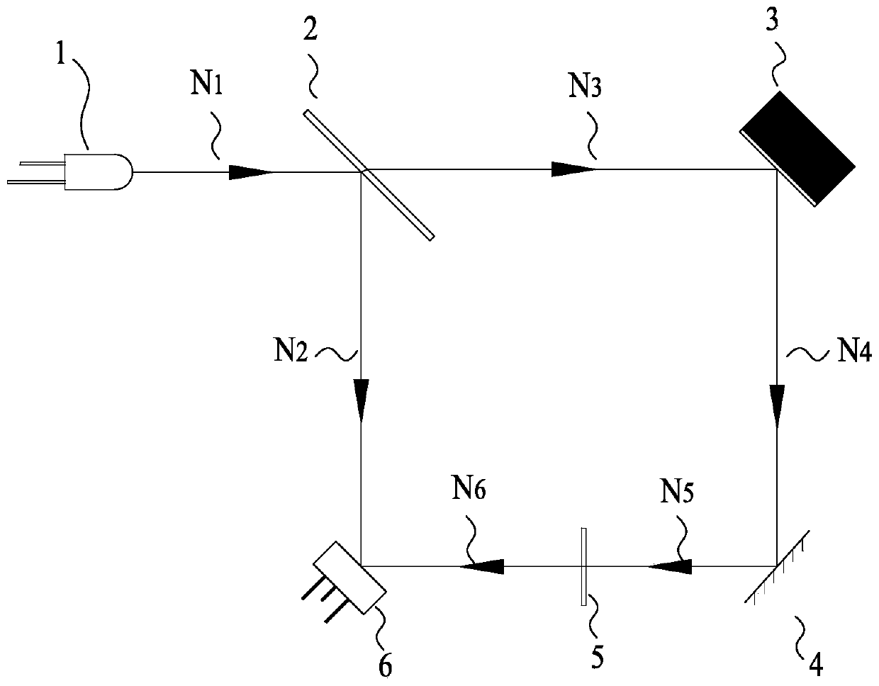
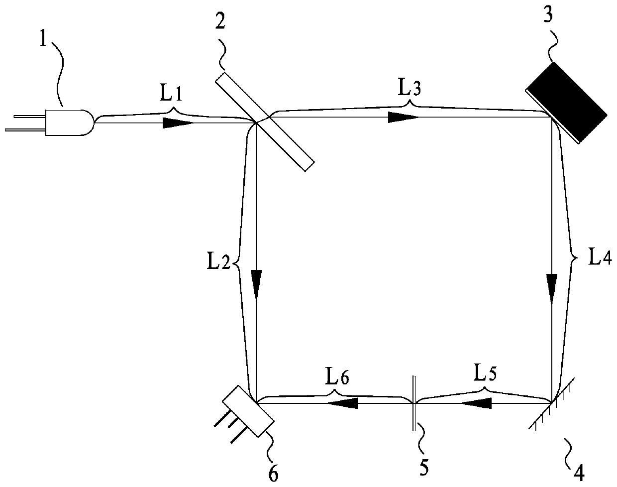
[0037] Such asfigure 1 , figure 2 As shown, a new in-situ dissolved oxygen monitoring device is optically connected by a green LED light source 1, a 50 / 50 flat beam splitter 2, a sample cell 3, a plane mirror 4, an optical filter 5, and a photocell 6, wherein the green The emission light path N1 of the LED light source 1 is provided with a 50 / 50 flat beam splitter 2, and the light path of the 50 / 50 flat beam splitter 2 and the green LED light source 1 is at an angle of 45 degrees; A photocell 6 is provided on the reflected optical path N2; a sample pool 3 is provided on the transmitted optical path N3 of the 50 / 50 flat beam splitter 2, and an oxidation-sensitive film is attached to the surface of the sample pool 3, and the oxidation-sensitive film on the surface of the sample pool 3 and the transmission The light path N3 is at an angle of 45 degrees; the transmitted light path N3 is projected on the light path N4 of the 90-degree reflection direction at the oxidation-sensitiv...
Embodiment 2
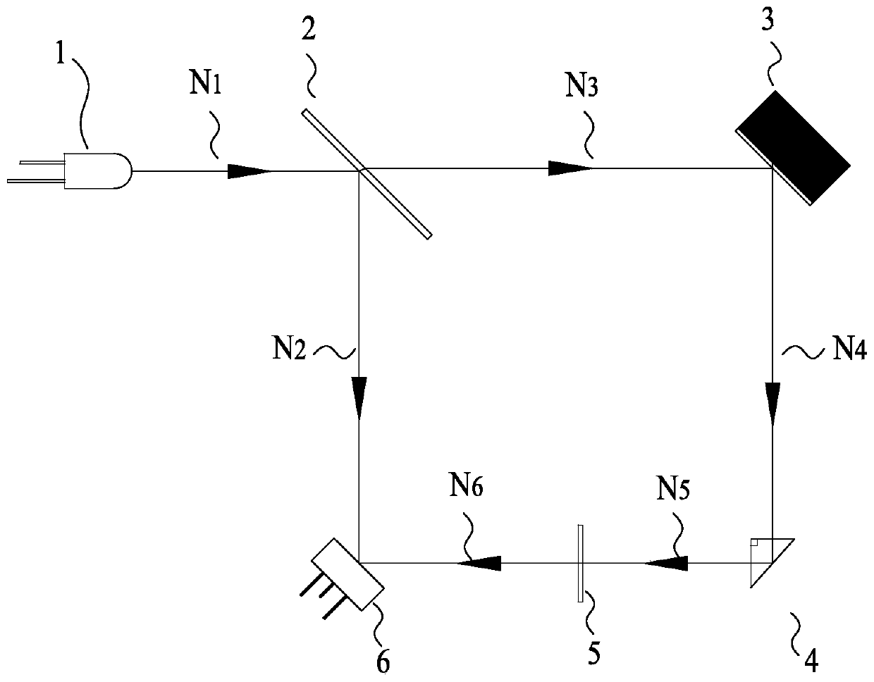
[0059] Such as image 3 As shown, the main difference between the second embodiment and the first embodiment is: the beam deflection element is a right-angled triangular prism; the bottom surface of the right-angled triangular prism is an isosceles right-angled triangle, and the two The length of the waist is 5mm, and the opposite side of the right angle is 7.1mm; the side of the optical path N4 perpendicular to the 90-degree angle is incident on the right-angled triangular prism and then transmitted vertically from the other side of the 90-degree angle, realizing the change of the 90-degree direction of the optical path N4 the goal of.
Embodiment 3
[0061] Such as Figure 4 As shown, the main difference between the third embodiment and the first embodiment is: the beam deflection element is a pentagonal prism; the bottom surface of the pentagonal prism is a pentagon, and the degree of one angle is 90 degrees. The degrees of the other four angles are 112.5 degrees; the length of the side opposite to the 90 degree angle is 5.2 mm, and the length of the other four sides is 8 mm; the light path N4 is perpendicular to the 90 degree angle and is incident on the inside of the pentaprism after internal reflection. The other side of the 90-degree angle is transmitted vertically, realizing the purpose of changing the direction of the optical path N4 by 90 degrees.
PUM
| Property | Measurement | Unit |
|---|---|---|
| wavelength | aaaaa | aaaaa |
Abstract
Description
Claims
Application Information
 - R&D
- Intellectual Property
- Life Sciences
- Materials
- Tech Scout
- Unparalleled Data Quality
- Higher Quality Content
- 60% Fewer Hallucinations
Browse by: Latest US Patents, China's latest patents, Technical Efficacy Thesaurus, Application Domain, Technology Topic, Popular Technical Reports.
© 2025 PatSnap. All rights reserved.Legal|Privacy policy|Modern Slavery Act Transparency Statement|Sitemap|About US| Contact US: help@patsnap.com


