Anti-fog swimming goggles based on thermoelectric power generation principle

A technology based on the principle of temperature difference power generation, applied in the field of swimming equipment, can solve the problems of easy fogging of swimming goggles

Active Publication Date: 2020-08-18
深圳市新胜嘉科技有限公司
View PDF6 Cites 0 Cited by
  • Summary
  • Abstract
  • Description
  • Claims
  • Application Information

AI Technical Summary

Problems solved by technology

[0005] The purpose of the present invention is to solve the problem that swimming goggles are prone to fogging, and to provide an anti-fog swimming goggle based on the principle of thermoelectric power generation that can automatically remove water mist

Method used


Image

  • Anti-fog swimming goggles based on thermoelectric power generation principle
  • Anti-fog swimming goggles based on thermoelectric power generation principle
  • Anti-fog swimming goggles based on thermoelectric power generation principle

Examples


Embodiment 1

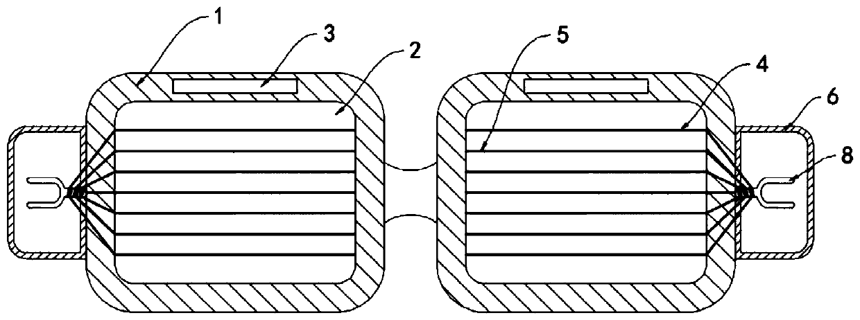
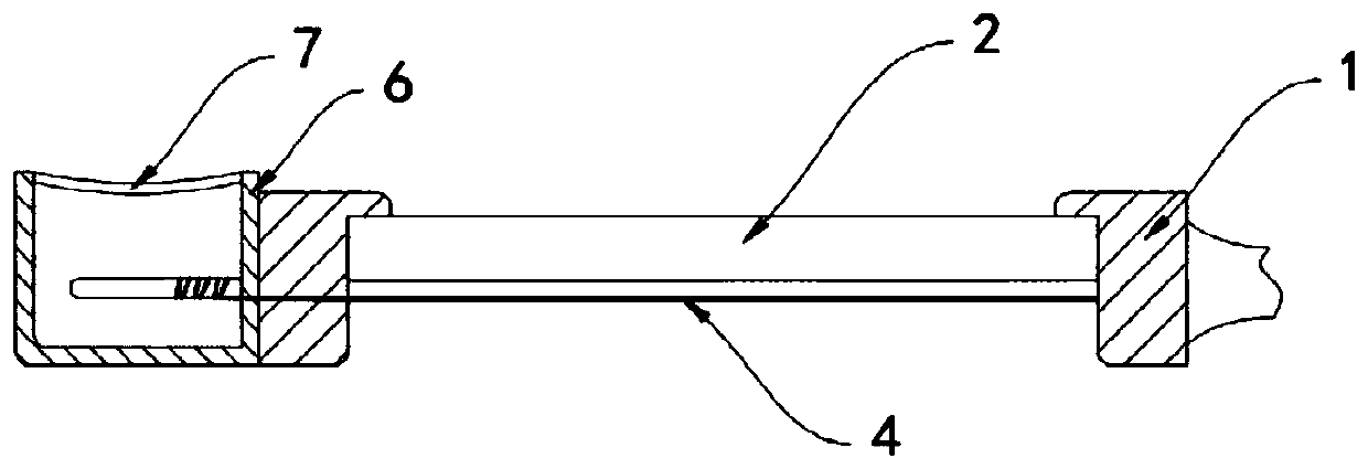
[0019] Such as Figure 1-2 As shown, a kind of anti-fog swimming goggles based on the principle of thermoelectric power generation, including a frame 1 and a lens 2 embedded in the frame 1, a ceramic temperature difference sheet 3 is fixedly embedded in the frame 1, and the electrodes at both ends of the ceramic temperature difference sheet 3 are respectively Located on the inner and outer sides of the lens 2, the electrodes at both ends of the ceramic temperature difference sheet 3 are electrically connected to a plurality of positive wires 4 and negative wires 5, both of which are made of indium tin oxide. The transparent conductive material does not affect the swimmer's normal line of sight. Both the positive lead wire 4 and the negative lead wire 5 extend to the inner surface of the lens 2 and are arranged in parallel at equal intervals. The side walls on both sides of the frame 1 are fixedly equipped with vibration boxes. 6. The side wall of the vibration box 6 facing the...

Embodiment 2

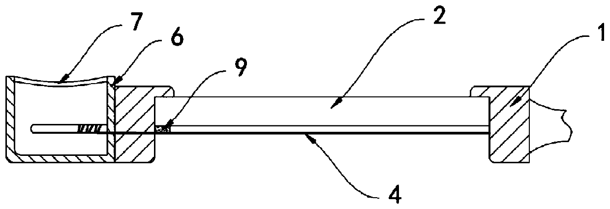
[0023] Such as image 3 As shown, the difference between this embodiment and Embodiment 1 is that a friction sheet 9 is attached to the inner wall of the mirror frame 1, and the friction sheet 9 is not fixed in contact with the positive lead wire 4 and the negative lead lead 5, and the positive lead wire 4 and the negative lead wire The outer surface of the wire 5 is coated with a wear-resistant coating at the position of the friction plate 9 .

[0024] In this embodiment, when the positive electrode lead 4 and the negative electrode lead 5 vibrate under the traction of the tuning fork rod 8, they rub against the friction plate 9 repeatedly, thereby generating heat, which is conducted to the surface of the lens 2 through the positive electrode lead 4 and the negative electrode lead 5, Speed ​​up the evaporation rate of water droplets.


PUM


Abstract

The invention belongs to the field of swimming equipment. The invention especially relates to anti-fog swimming goggles based on a thermoelectric power generation principle. The glasses comprise a glasses frame and lenses embedded in the glasses frame, and a ceramic temperature difference sheet is fixedly embedded in the glasses frame; electrodes at two ends of the ceramic temperature difference sheet are respectively positioned on the inner and outer sides of the lens; electrodes at the two ends of the ceramic temperature difference sheet are electrically connected with a plurality of positive wires and negative wires respectively; the positive electrode wire and the negative electrode wire extend to the inner side surface of the lens; vibration boxes are fixedly installed on the side walls of the two sides of the mirror frame, the side walls of the sides, facing water flow, of the vibration boxes are composed of tympanic membrane plates, tuning fork rods are installed on the side walls of the vibration boxes, and the vibration frequency of the tuning fork rods is consistent with that of the tympanic membrane plates. Water drops on the inner side of the mirror surface can be subjected to two physical reactions of heating evaporation and water electrolysis at the same time and quickly disappear completely, a good anti-fog and water removal effect is achieved, and the sight of aswimmer is prevented from being affected.

Description

technical field [0001] The invention belongs to the field of swimming equipment, in particular to an anti-fog swimming goggle based on the principle of thermoelectric power generation. Background technique [0002] Swimming goggles are essential protective equipment for swimming. They can be attached to the eyes of swimmers to prevent swimming pool water from entering the glasses, so that swimmers can remain visible underwater, which not only increases the fun of swimming, but also Played the role of security protection. [0003] However, most of the traditional swimming goggles have the problem of lens fogging and blocking the sight of swimmers when they are in use. When the hot gas contacts the swimming goggles, it will condense and fog up, which will affect the normal swimming movement. It is very troublesome to take off the swimming goggles to wipe the water mist from time to time. However, the anti-fog effect of the anti-fog coating will be greatly reduced after repea...

Claims


Application Information

Patent Timeline
IPC IPC(8): A63B33/00
CPCA63B33/002
Inventor 司友兰
Owner 深圳市新胜嘉科技有限公司
Why Eureka
Try Eureka