
Horizontal roller suction collating machine

A horizontal roller and page machine technology, applied in the field of book collating machines, can solve problems such as product quality degradation, damage to paper 4, and increased closing speed of gripper teeth 3, so as to achieve a smooth and soft release process, improve product quality, The effect of improving paging efficiency

Active Publication Date: 2020-08-18
淮北平坤锂电池科技有限公司
View PDF4 Cites 0 Cited by
  • Summary
  • Abstract
  • Description
  • Claims
  • Application Information

AI Technical Summary

Problems solved by technology

[0003] First, when the suction nozzle 2 and the gripper 3 are clamping the paper 5, because the cam drives the gripper 3 to rotate, which is a mechanical movement, the thickness of the paper 5 cannot be accurately measured, and the clamping force is prone to be too large , so that the paper 5 has an indentation, or the clamping force is too small to pull the paper 5 out, and then the phenomenon of page loss and paper jam occurs, and the gripper 3 is in the process of closing. The paper 5 at the gap causes local impact, which is easy to cause damage to the paper 4, resulting in a decline in product quality
[0004] Its two, because the diameter of rotary drum 1 is fixed, then can't adjust according to the length of paper 5, once the length of paper 5 exceeds half of the circumference of the section of rotary drum 1, then paper 5 covers another gripper 3, The speed of collating pages of the collating machine will be greatly reduced. At the same time, the constant diameter of the rotating roller 1 will greatly restrict the rotating speed of the rotating roller 1. If the speed is too high, the closing speed of the gripper teeth 3 will increase accordingly. If the speed is too high, the damage to the paper will be increased; if the speed is too slow, the paging speed will be affected
[0005] Third, when the paper 5 is transported to the page box 6, the paging roller 7 collides with the paper 5, which will easily cause creases to appear on the paper 5, further affecting the quality of the paper 5, and causing a decline in the quality of the product

Method used


Image

  • Horizontal roller suction collating machine
  • Horizontal roller suction collating machine
  • Horizontal roller suction collating machine

Examples


Embodiment Construction

[0025] The following will clearly and completely describe the technical solutions in the embodiments of the present invention with reference to the accompanying drawings in the embodiments of the present invention. Obviously, the described embodiments are only some, not all, embodiments of the present invention. Based on the embodiments of the present invention, all other embodiments obtained by persons of ordinary skill in the art without making creative efforts belong to the protection scope of the present invention.

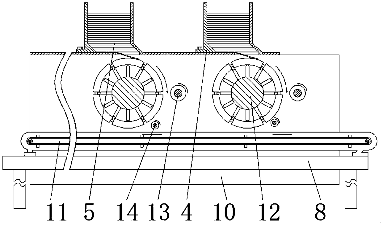
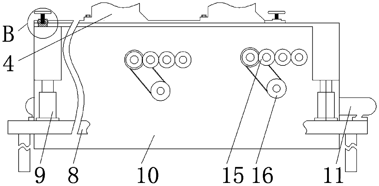
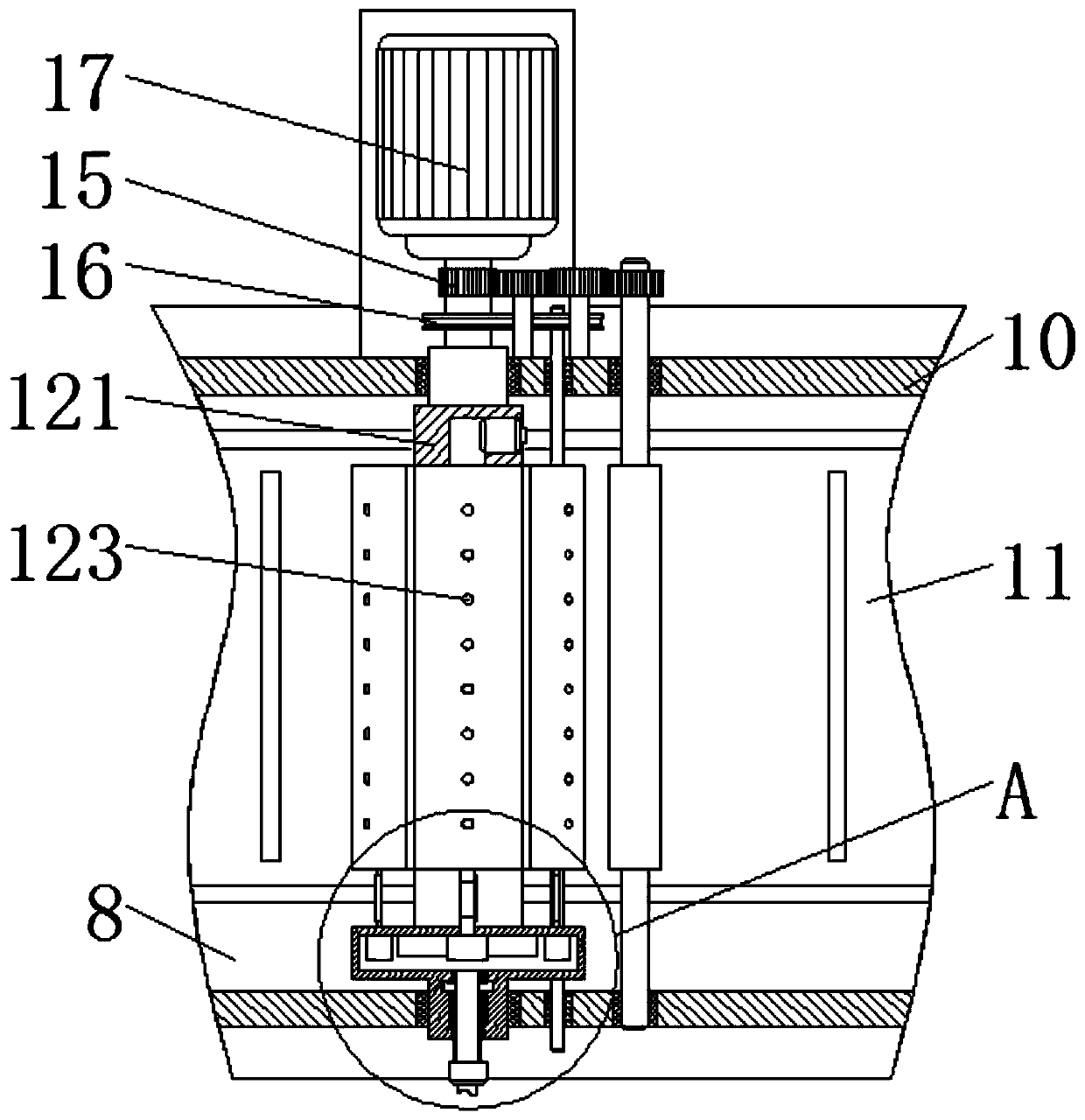
[0026] see Figure 1-7 , a horizontal roller suction collating machine, including a base 8, paper 5, a conveyor belt 11, an air pump and a hydraulic pump, the four corners of the upper surface of the base 8 are respectively fixed with a hydraulic lifting device 9, and the top of the hydraulic lifting device 9 The side panel 10 is fixedly installed, and the side panel 10 is movably clamped with the hydraulic lifting device 9. The conveyor belt 11 is fixedly con...


PUM


Abstract

The invention relates to the technical field of book collating machines, and discloses a horizontal roller suction collating machine. The horizontal roller suction collating machine comprises a base,paper, a conveying belt, a pneumatic pump and a hydraulic pump. By arranging center shafts and pressure sealing devices, the paper is integrally sucked; on the one hand, sufficient tension on the paper is provided, the harm of grippers to the paper is avoided, the safety of the paper is improved, the situation that the tail of the paper hits against the equipment in the rotating process of the center shafts is prevented, the damage of the paper is reduced, and the product quality is improved; and on the other hand, uninterrupted collating can be achieved, the outer surfaces of the pressure sealing devices are efficiently utilized, the collating speed is increased, and the collating efficiency is improved. Meanwhile, by arranging expanding devices, the diameter of the collating device is regulated and controlled, the diameter of the collating device can be selected according to the length of the paper, at least two pieces of paper can be collated when the collating device rotates by onecircle, and the collating efficiency is further improved.

Description

technical field [0001] The invention relates to the technical field of book collating machines, in particular to a horizontal roller suction collating machine. Background technique [0002] The collating machine is to match papers with different page numbers together. It can be divided into clamp type and roller type collating machine. The working principle of the roller type collating machine is as follows Figure 8 As shown: the rotating roller 1 rotates, and drives the suction nozzle 2 and the gripper 3 to rotate. When it rotates to the gap below the storage box 4, the cam installed on the rotating roller 1 controls the movement of the gripper 3. Open and close, clamp the paper 5, and then rotate again, carry the paper 5, turn to the page box 6, the suction nozzle 2 and the gripper 3 are separated, the paper 5 is released, and the page roller 7 is used to dial move to make the paper 5 return to its original position, but there are some deficiencies in this process, as fol...

Claims


Application Information

Patent Timeline
Patent Type & Authority Applications(China)
IPC IPC(8): B65H5/02B65H3/10B65H5/06
CPCB65H3/10B65H5/021B65H5/06
Inventor 叶小英
Owner 淮北平坤锂电池科技有限公司
Learn More