System for detecting piston error between adjacent spliced mirrors

An error detection and sub-mirror technology, applied in the direction of testing optical performance, etc., can solve problems such as difficulty in selecting filters that meet specific needs, non-common optical path errors, and engineering application difficulties, to overcome the 2π blur effect and increase the detection range. , the range of dynamic adjustable effects

Active Publication Date: 2020-08-18
CHANGCHUN INST OF OPTICS FINE MECHANICS & PHYSICS CHINESE ACAD OF SCI
View PDF5 Cites 5 Cited by
  • Summary
  • Abstract
  • Description
  • Claims
  • Application Information

AI Technical Summary

Problems solved by technology

However, in the actual application process, the technical measurement results based on monochromatic light sources are modulated by the wavelength of monochromatic light and appear periodic changes, resulting in 2π blurring effect
The 2π fuzzy effect makes the measurement range based on the monochromatic light measurement technology become ±λ due to the influence of the monochromatic light wavelength, thus greatly reducing the application range of the technology
Although the technology based on polychromatic light sources solves the 2π blur effect in monochromatic light source technology to a certain extent, it also introduces a series of other problems. For example, the selection of polychromatic light sources requires accurate calculation of the wavelength of the selected light source, and multiple Chromatic lasers will introduce non-common optical path errors; although it is simple and easy to use fi

Method used


Image

  • System for detecting piston error between adjacent spliced mirrors
  • System for detecting piston error between adjacent spliced mirrors
  • System for detecting piston error between adjacent spliced mirrors

Examples


Embodiment Construction

[0040] The following will clearly and completely describe the technical solutions in the embodiments of the present invention with reference to the accompanying drawings in the embodiments of the present invention. Obviously, the described embodiments are only some, not all, embodiments of the present invention. Based on the embodiments of the present invention, all other embodiments obtained by persons of ordinary skill in the art without making creative efforts belong to the protection scope of the present invention.

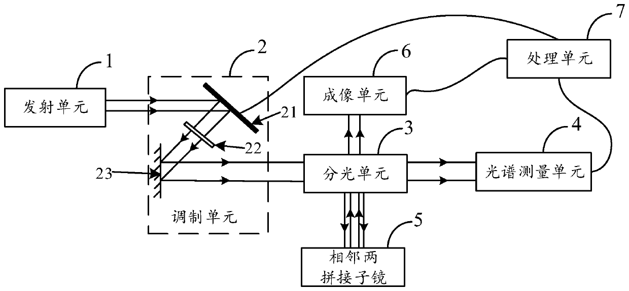
[0041] The invention provides a piston error detection system between adjacent splicing mirrors, such as figure 1 As shown, it includes: an emission unit 1, a modulation unit 2, a spectroscopic unit 3, a spectrum measurement unit 4, two adjacent splicing sub-mirrors 5, an imaging unit 6 and a processing unit 7; wherein,

[0042] Emitting unit 1, for providing broadband light;

[0043] The modulation unit 2 includes a spatial light modulator (SLM) 21 and a sca...


PUM


Abstract

The invention discloses a system for detecting a piston error between adjacent spliced mirrors, and the system comprises: a transmitting unit which is used for providing broadband light; a modulationunit which comprises a spatial light modulator and a scattering medium and is used for dynamically modulating broadband light; a light splitting unit which is used for splitting light and respectivelytransmitting the light to the spectral measurement unit and the reflecting surface of the splicing sub-mirror; a spectral measurement unit which is used for measuring spectral distribution modulatedby the spatial light modulator and the scattering medium; a splicing sub-mirror which is used for reflecting the light beam split by the light splitting unit to the imaging unit; an imaging unit whichis used for collecting diffraction patterns; and a processing unit which is used for controlling the spatial light modulator to adjust the spectral shape and distribution to a specified shape, and isalso used for analyzing and processing the diffraction pattern to obtain a piston error value between two adjacent spliced sub-mirrors. According to the system, the 2pi fuzzy effect is overcome, thedetection range of the piston error of the adjacent splicing mirrors is dynamically adjustable, and a large measurement range and high measurement precision can be realized at the same time.

Description

technical field [0001] The invention relates to the field of detection of spliced ​​mirrors, in particular to a detection system for piston errors between adjacent spliced ​​mirrors. Background technique [0002] The resolution capability of the ground-based telescope imaging system is related to factors such as the telescope's aperture, observation wavelength, and atmospheric seeing. The effect of atmospheric seeing can be well corrected by adaptive optics technology. Under a specific observation wavelength, the ground-based telescope's The resolving power of the imaging system is directly proportional to the effective aperture of the telescope, but with the continuous progress of astronomy, astronomers put forward higher requirements on the aperture of the telescope in order to observe astronomical targets deeper in the universe. However, limited by a series of factors such as mirror blank preparation, optical processing, transportation and adjustment, structural design, a...

Claims


Application Information

Patent Timeline
IPC IPC(8): G01M11/02
CPCG01M11/02
Inventor 杨飞曹海峰安其昌张景旭
Owner CHANGCHUN INST OF OPTICS FINE MECHANICS & PHYSICS CHINESE ACAD OF SCI
Why Eureka
Try Eureka