
Jig applied to high-pressure flushing of packaged chip

A technology for high-pressure washing and chip loading, which is applied in the manufacture of electrical components, semiconductor/solid-state devices, circuits, etc. It can solve the problems of lead washing deformation, overflow washing is not clean, easy to damage leads, etc., and achieve the effect of improving packaging efficiency

Inactive Publication Date: 2020-08-18
杭州易正科技有限公司
View PDF0 Cites 0 Cited by
  • Summary
  • Abstract
  • Description
  • Claims
  • Application Information

AI Technical Summary

Problems solved by technology

[0002] At present, the chip packaging process includes chip bonding, silver paste curing, lead welding, light inspection, injection molding, laser typing, high temperature curing, despilling, electroplating annealing, rib cutting and molding, etc.; Injection plastic between the leads around the chip; the existing excess flash is removed by cutting, but cutting is easy to damage the leads, so it is proposed to use weak acid to immerse the lead part, soak the flash together, and then rinse with high-pressure water to remove the overflow Wash away
In the existing flushing process, due to the high pressure of the water jet, it is easy to cause the deformation of the lead part, and when the water jet is small, the overflow on the packaged chip cannot be washed cleanly, so it is necessary to design a fixture to meet the flushing requirements. Does not cause lead flush deformation

Method used


Image

  • Jig applied to high-pressure flushing of packaged chip
  • Jig applied to high-pressure flushing of packaged chip
  • Jig applied to high-pressure flushing of packaged chip

Examples


Embodiment

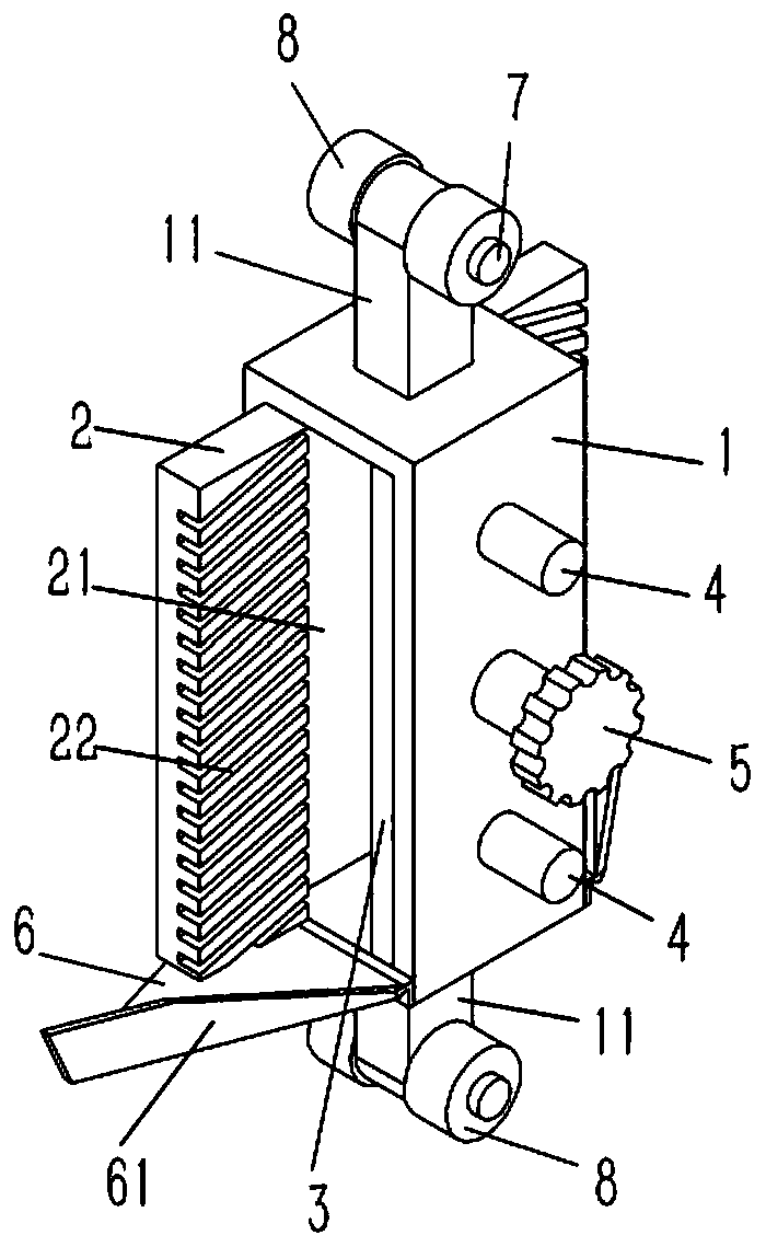
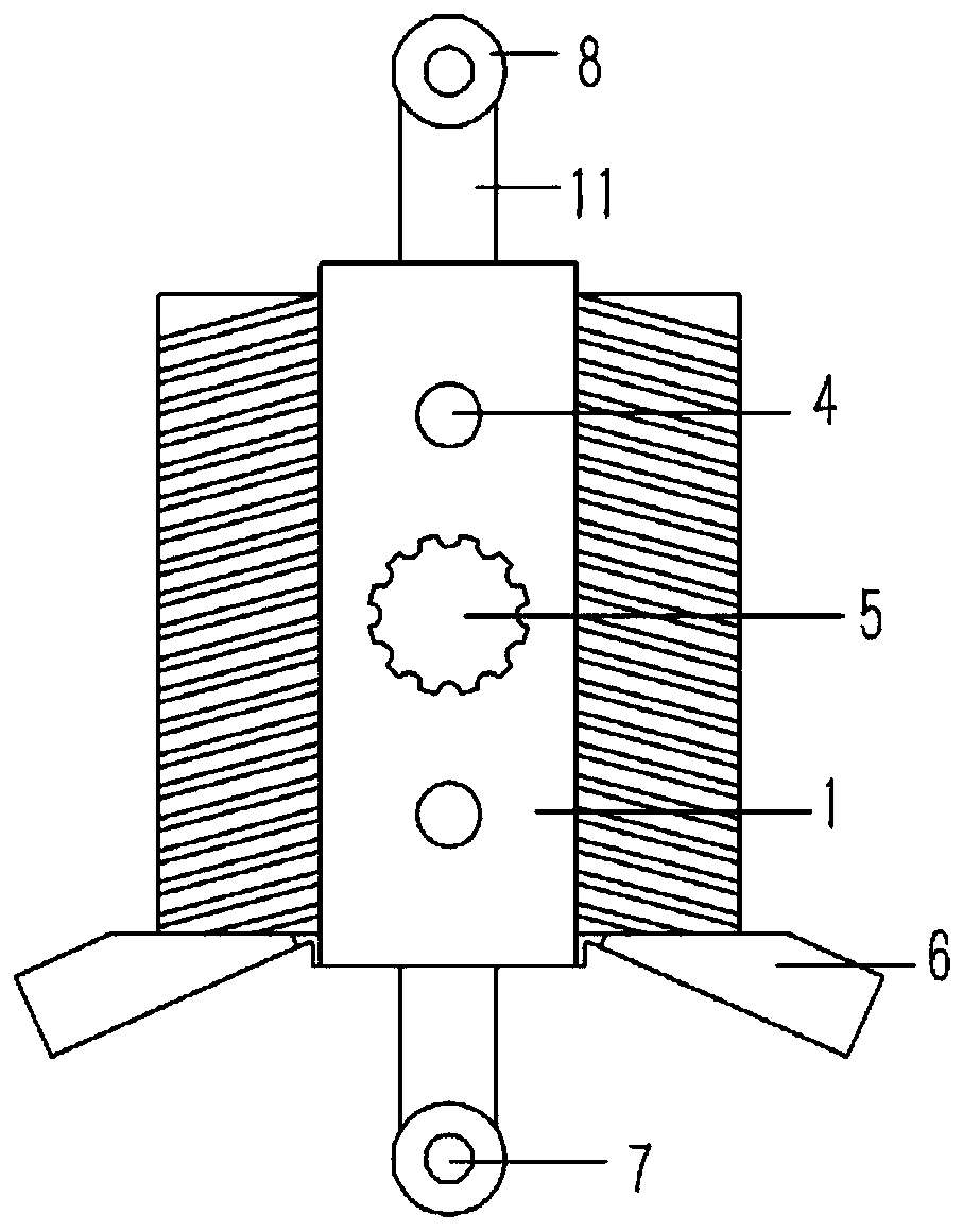
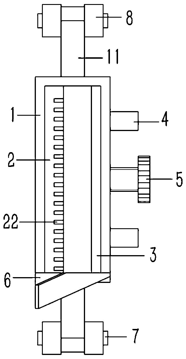
[0020] Example: see Figures 1 to 3 As shown, a jig for high-pressure flushing of packaged chips includes an upright and rectangular positioning frame 1, openings are formed on the left and right sides of the positioning frame 1, and supports are formed on the upper and lower end surfaces of the positioning frame 1. Ears 11, a vertical pin shaft 7 is plugged into the lug 11, the two ends of the pin shaft 7 are inserted and fixed with rollers 8; A rectangular positioning groove 21 is formed, and the two sides of the rear splint 2 protrude from the positioning frame 1 to form a number of oblique discharge grooves 22, and the front splint 3 is inserted into the positioning frame 1 on the front side of the rear splint 2; The front end surface of the positioning frame 1 is plugged with several longitudinal guide posts 4, the rear ends of the guide posts 4 are fixed on the front splint 3, and the front end surface of the positioning frame 1 between the guide posts 4 is screwed with ...


PUM


Abstract

The present invention discloses a jig applied to the high-pressure flushing of a packaged chip. The jig comprises a vertical and rectangular positioning frame, openings are formed at the left side andthe right side of the positioning frame, and supporting lugs are formed on the upper end face and the lower end face of the positioning frame. Longitudinal pin shafts are connected to the supportinglugs in an inserted manner, and idler wheels are fixed to the two ends of each pin shaft in an inserted and sleeved manner. A rear clamping plate is fixed to the inner wall of the rear side of the positioning frame, a rectangular positioning groove is formed in the middle of the rear clamping plate, and the two sides of the rear clamping plate extend out of the positioning frame to form a plurality of inclined discharging grooves. A front clamping plate is inserted into the positioning frame at the front side of the rear clamping plate, a plurality of longitudinal guide columns are inserted into the front end face of the positioning frame, and the rear ends of the guide columns are fixed to the front clamping plate. Bolts are connected to the positions, between the guide columns, of the front end face of the positioning frame in a threaded mode, and the tail ends of the bolts are hinged to the rear clamping plate.

Description

technical field [0001] The invention relates to the technical field of chip packaging equipment, in particular to a jig used for high-pressure flushing of packaged chips. Background technique [0002] At present, the chip packaging process includes chip bonding, silver paste curing, lead welding, light inspection, injection molding, laser typing, high temperature curing, despilling, electroplating annealing, rib cutting and molding, etc.; Injection plastic between the leads around the chip; the existing excess flash is removed by cutting, but cutting is easy to damage the leads, so it is proposed to use weak acid to immerse the lead part, soak the flash together, and then rinse with high-pressure water to remove the overflow Material washed away. In the existing flushing process, due to the high pressure of the water jet, it is easy to cause the deformation of the lead part, and when the water jet is small, the overflow on the packaged chip cannot be washed cleanly, so it i...

Claims


Application Information

Patent Timeline
IPC IPC(8): H01L21/67
CPCH01L21/67051
Inventor 徐俊
Owner 杭州易正科技有限公司
Features
  • Generate Ideas
  • Intellectual Property
  • Life Sciences
  • Materials
  • Tech Scout
  • Unparalleled Data Quality
  • Higher Quality Content
  • 60% Fewer Hallucinations
Learn More