Drying equipment for spraying assembly line

A technology of drying equipment and assembly line, which is applied to devices for coating liquid on surfaces, coatings, pre-treatment surfaces, etc., can solve the problems of high energy consumption, affect the quality of workpieces, low drying efficiency, etc., and achieve a simple device structure. , The effect of reducing production cost and high drying efficiency

Pending Publication Date: 2020-08-21
苏州开泰利环保能源有限公司
View PDF0 Cites 2 Cited by
  • Summary
  • Abstract
  • Description
  • Claims
  • Application Information

AI Technical Summary

Problems solved by technology

[0003] Most of the drying methods used in the prior art use convection drying and radiation drying. The convection drying moves the workpiece to be dried to the drying device, heats up the drying device, and puts the drying device into the drying device. The air is gradually heated to the drying temperature, and then the product is gradually dried. The heating speed is slow, and the drying time often reaches several hours. The drying efficiency is low and the production efficiency is reduced.
After the drying step is completed, open the drying device and move the next workpiece into the drying device. During the opening process, the drying device often transfers the high-temperature airflow inside it to the outside air quickly, so that the drying device is in the second When drying the workpiece for the first time, the temperature in the drying device is gradually raised to the drying temperature. Therefore, the convection drying method has low drying efficiency, rapid temperature loss, high energy consumption, and high production costs;
[0004] The radiative drying method used in the prior art is often to install an infrared lamp tube inside the drying device, and use the infrared lamp tube to radiate and heat the product for drying. This drying method has high drying efficiency, but the workpiece will be dried after entering the drying device , the side of the product can only be partially dried through the infrared lamp installed on the inner wall of the drying device, and the end faces at both ends cannot be dried by the infrared lamp, and at the same time, it is impossible to target the complex structure of the product when facing a workpiece with a relatively complex structure. Drying, such as the above-mentioned medium oil tank body, its bottom mechanism is complex, and the drying effect cannot be achieved by heating with conventional infrared lamps, but the use of long-term radiation heating to increase the internal temperature of the drying device often leads to partial The area is heated by radiation for a long time and affects the quality of the workpiece

Method used


Image

  • Drying equipment for spraying assembly line
  • Drying equipment for spraying assembly line
  • Drying equipment for spraying assembly line

Examples


Embodiment Construction

[0030] The following will clearly and completely describe the technical solutions in the embodiments of the present invention with reference to the accompanying drawings in the embodiments of the present invention. Obviously, the described embodiments are only some, not all, embodiments of the present invention. Based on the embodiments of the present invention, all other embodiments obtained by persons of ordinary skill in the art without making creative efforts belong to the protection scope of the present invention.

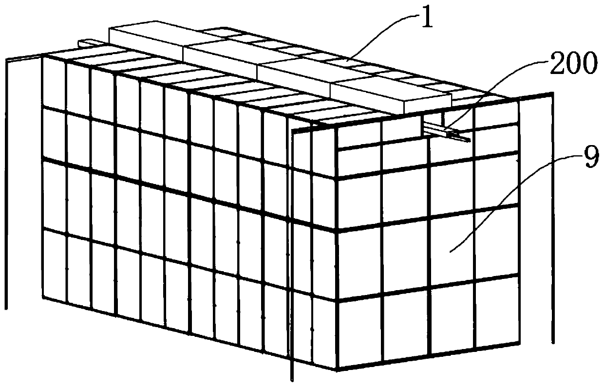
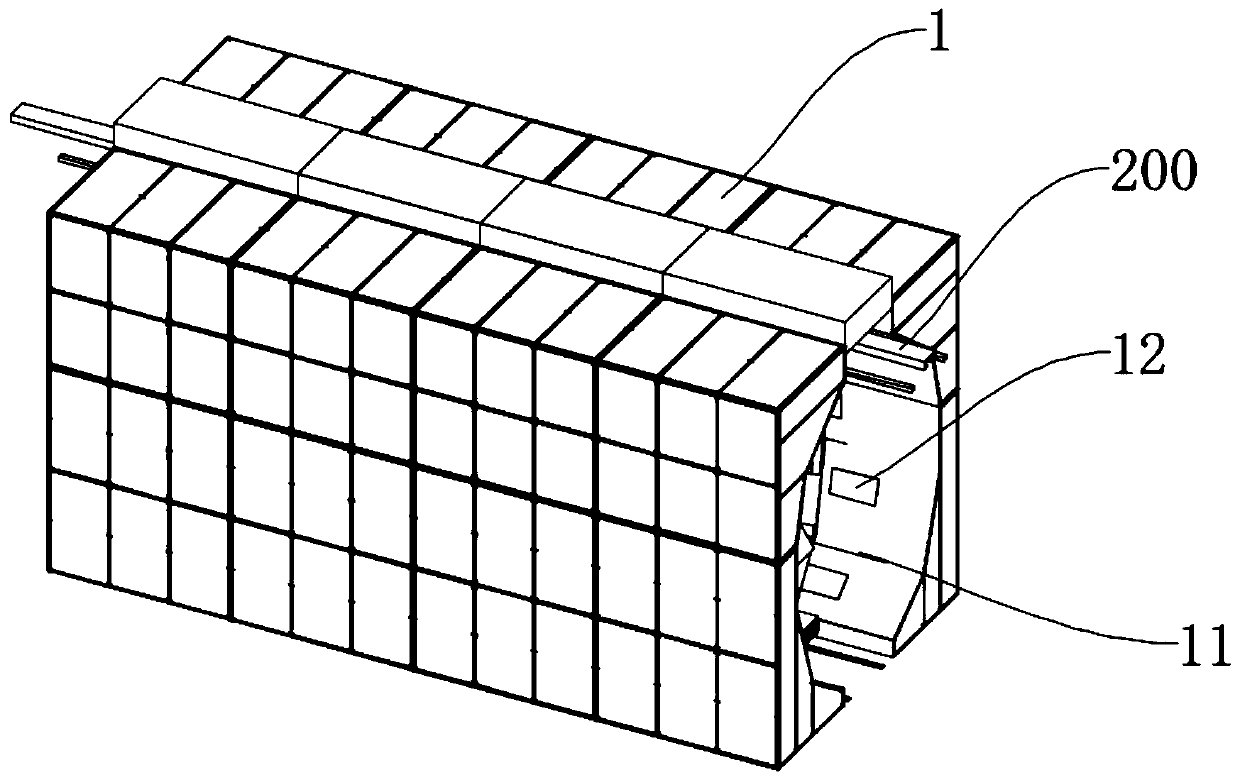
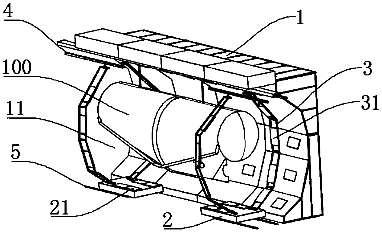
[0031] Such as figure 1 , figure 2 with image 3 The shown drying equipment for a spraying assembly line includes an equipment body 1, the equipment body 1 is provided with a drying channel 11 and a first infrared light-emitting part 12 located on the inner wall of the drying channel 11, and the first infrared light-emitting The radiation heating surface of the part 12 faces the drying channel 11; the spraying line includes a track assembly 200 for installi...


PUM


Abstract

The invention discloses drying equipment for a spraying assembly line, comprising an equipment body. The equipment body is provided with a drying channel and a first infrared light-emitting part located on the inner wall of the drying channel. A movable assembly is arranged inside the drying channel and can move along an extending direction of the drying channel. The movable assembly is provided with a rotatable support, and the rotatable support is provided with a second infrared light-emitting part. The rotatable support has a first position state and a second position state. When the rotatable support is in the first position state, a radiation direction of the second infrared light-emitting part is the same as the radiation direction of the first infrared light-emitting part. When therotatable support is in the second position state, the radiation direction of the second infrared light-emitting part faces the extending direction of the drying channel. The drying equipment for thespraying assembly line can fully dry the outer surface of a workpiece, and has high drying efficiency, low energy consumption, reduced production cost, strong flexibility and wide application.

Description

technical field [0001] The invention relates to the field of infrared drying, in particular to a drying equipment for a spraying assembly line. Background technique [0002] With the advancement and development of science and technology, industrial products gradually use assembly line operations in spraying operations to improve work efficiency. Some large workpieces, such as the tank body on the tank truck, are hoisted on the assembly line for spraying work in order to ensure its spraying effect and spraying efficiency, but after the spraying process is completed, the sprayed product needs to be dried by a drying device. Drying, because the assembly line work is to move the product directly along the assembly line to the inside of the drying device for drying. [0003] Most of the drying methods used in the prior art use convection drying and radiation drying. The convection drying moves the workpiece to be dried to the drying device, heats up the drying device, and puts t...

Claims


Application Information

Patent Timeline
Patent Type & Authority Applications(China)
IPC IPC(8): B05D3/02
CPCB05D3/0263
Inventor 王新如潘嵩李磊刘奕巧魏袆璇吴金顺刘猛张意祥
Owner 苏州开泰利环保能源有限公司
Why Eureka
Try Eureka