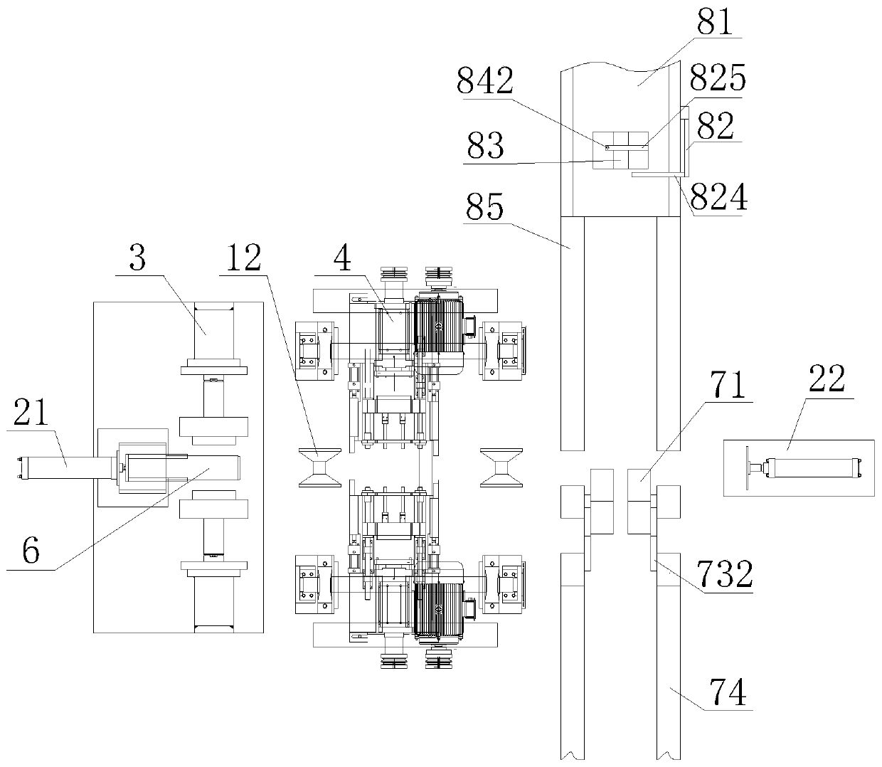
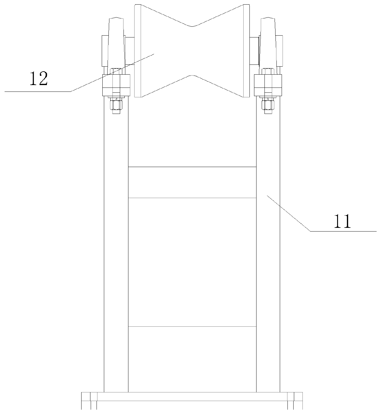
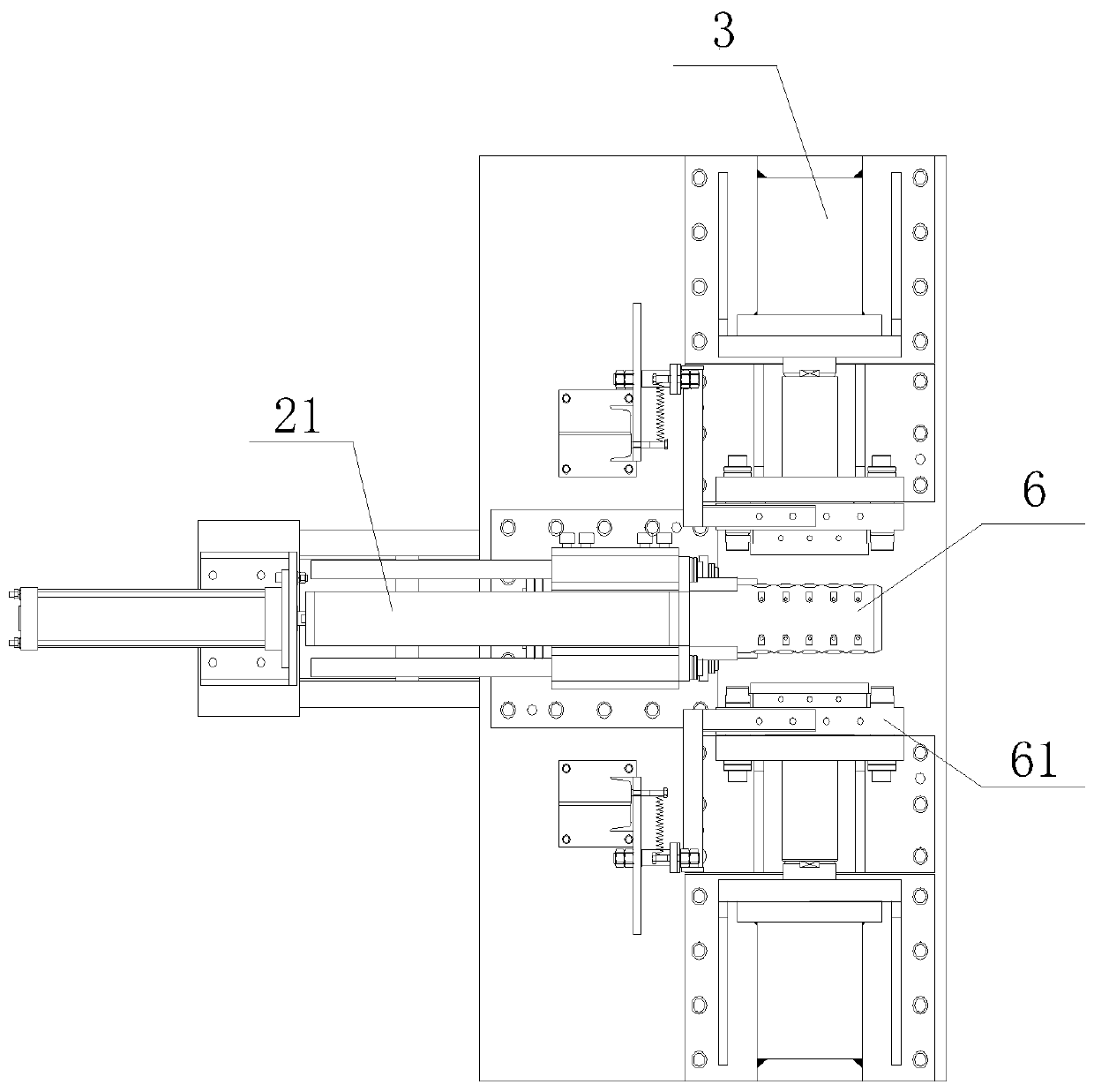
Automatic punching and drilling integrated loading and unloading equipment

A technology of loading and unloading equipment and punching device, applied in the field of steel pipe processing, can solve the problems of slow production efficiency, increased labor intensity of operators, complicated processing and production process, etc.

Active Publication Date: 2020-08-21
潍坊东方钢管有限公司
View PDF9 Cites 2 Cited by
  • Summary
  • Abstract
  • Description
  • Claims
  • Application Information

AI Technical Summary

Problems solved by technology

[0002] So far, in the machining industry, when machining square holes (such as regular hexagonal holes) at the end of rods, it includes two steps of drilling and punching, but the current processing flow and processing equipment are independent of each other. Drilling equipment and punching equipment complete the processing process independently, and after the drilling process is completed, the rods must be taken out from the drilling equipment by manual bearers and put into the punching equipment for punching, processing and production The process is complicated, the production cycle is greatly extended, the production efficiency is slow, and the production equipment purchase cost and the labor intensity of the operator are increased, making production and operation extremely inconvenient
[0003] The document with the application number CN201220327337.X discloses an integrated machine for drilling and punching rods, which can complete the drilling and punching of rods in one step, which simplifies the production process. During the hole process, the bar nee

Method used


Image

  • Automatic punching and drilling integrated loading and unloading equipment
  • Automatic punching and drilling integrated loading and unloading equipment
  • Automatic punching and drilling integrated loading and unloading equipment

Examples


Embodiment Construction

[0029]In order to make the objectives, technical solutions and advantages of the present invention clearer, the present invention will be described in further detail below in conjunction with the accompanying drawings and embodiments. It should be understood that the specific embodiments described here are only used to explain the present invention and are not intended to limit the invention.

[0030] It should be noted that, in the description of the present invention, terms such as "upper", "lower", "left", "right", "inner", "outer" and other indicated directions or positional relationships are based on the terms shown in the accompanying drawings. The direction or positional relationship shown is only for convenience of description, and does not indicate or imply that the device or element must have a specific orientation, be constructed and operated in a specific orientation, and thus should not be construed as limiting the present invention.

[0031] In addition, it shoul...


PUM

PropertyMeasurementUnit
Bending angleaaaaaaaaaa

Abstract

The invention is applicable to the technical field of steel pipe machining, and provides automatic punching and drilling integrated loading and unloading equipment. The automatic punching and drillingintegrated loading and unloading equipment comprises a supporting device, a fixing device, a punching device, a drilling device and an automatic conveying device, wherein the supporting device comprises a supporting frame and a plurality of guide seats; the punching device is positioned at one side of a left fixing piece; the drilling device is positioned at one side of the punching device; the automatic conveying device comprises a conveyer and a discharging device; and the discharging device comprises symmetrical moving devices, the moving devices comprise bottom plates, telescopic pieces,a plurality of connecting rods and guide rods, the connecting rods comprise a first connecting rod and second connecting rods, one ends of the second connecting rods are movably connected with the output ends of the telescopic pieces, the other ends of the second connecting rods are connected with the guide rods through fixing blocks, the ends of the telescopic pieces are movably connected with the guide rods, and the bottom plates are positioned below guide seats. In this way, the automatic punching and drilling integrated loading and unloading equipment realizes automatic guiding transportation and automatic discharging transportation of steel pipes, meanwhile, realizes automatic drilling and punching, and improves working efficiency.

Description

technical field [0001] The invention relates to the technical field of steel pipe processing, in particular to an automatic integrated loading and unloading equipment for punching and drilling. Background technique [0002] So far, in the machining industry, when machining square holes (such as regular hexagonal holes) at the end of rods, it includes two steps of drilling and punching, but the current processing flow and processing equipment are independent of each other. Drilling equipment and punching equipment complete the processing process independently, and after the drilling process is completed, the rods must be taken out from the drilling equipment by manual bearers and put into the punching equipment for punching, processing and production The process is complicated, the production cycle is greatly extended, the production efficiency is slow, and the production equipment purchase cost and the labor intensity of the operator are increased, and the production and ope...

Claims


Application Information

Patent Timeline
IPC IPC(8): B23P23/04B23Q7/00B21D28/34B21D28/28B21D43/00B21D43/02B21D45/04
CPCB23P23/04B23Q7/00B21D28/34B21D28/28B21D43/003B21D43/006B21D43/02B21D45/04Y02P70/10
Inventor 李延海徐传敏李仁宾李习林崔志民
Owner 潍坊东方钢管有限公司
Why Eureka
Try Eureka