
Automobile belt pulley electroplating equipment

A technology of electroplating equipment and pulleys, which is applied in the electrolysis process, electrolysis components, cells, etc., can solve problems affecting quality, uneven electroplating, and electroplating effects in holes and bottoms of holes, etc., to prevent pollution, improve electroplating quality, and ensure The effect of finished product quality

Inactive Publication Date: 2020-08-21
钟国财
View PDF0 Cites 1 Cited by
  • Summary
  • Abstract
  • Description
  • Claims
  • Application Information

AI Technical Summary

Problems solved by technology

[0003] The pulley needs to be electroplated during the production process, and when the existing electroplating equipment is electroplating, water film and air bubbles are easily formed in the blind hole or through hole on the pulley, which will affect the electroplating effect in the hole and at the bottom of the hole, making Uneven electroplating affects the quality. Therefore, in view of the above status quo, it is urgent to develop an electroplating equipment for automobile pulleys to overcome the shortcomings in current practical applications.

Method used


Image

  • Automobile belt pulley electroplating equipment
  • Automobile belt pulley electroplating equipment
  • Automobile belt pulley electroplating equipment

Examples


Embodiment 1

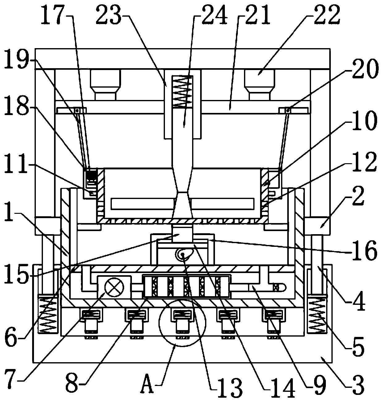
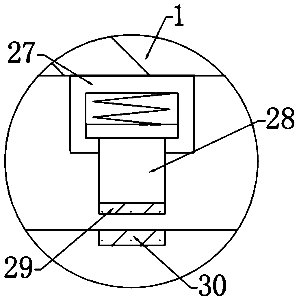
[0026] see Figure 1-3 , in an embodiment of the present invention, an automobile pulley electroplating equipment includes an electroplating tank 1, the left and right sides of the electroplating tank 1 are fixedly connected with support blocks 2, and the bottom of the support block 2 is provided with a shock absorbing mechanism. The top of the support block 2 is fixedly connected with a fixed bar, and the top of the fixed bar is fixedly connected with a top plate, and the underside of the top plate is provided with a placement mechanism for fixing the pulley, and the placement mechanism is connected with the top plate by a lifting mechanism.

Embodiment 2

[0028] In this embodiment, the lifting mechanism includes a connecting plate 21 arranged on the lower side of the top plate, the connecting plate 21 is slidably connected with the support rod, and a telescopic rod 22 is fixedly connected between the connecting plate 21 and the top plate.

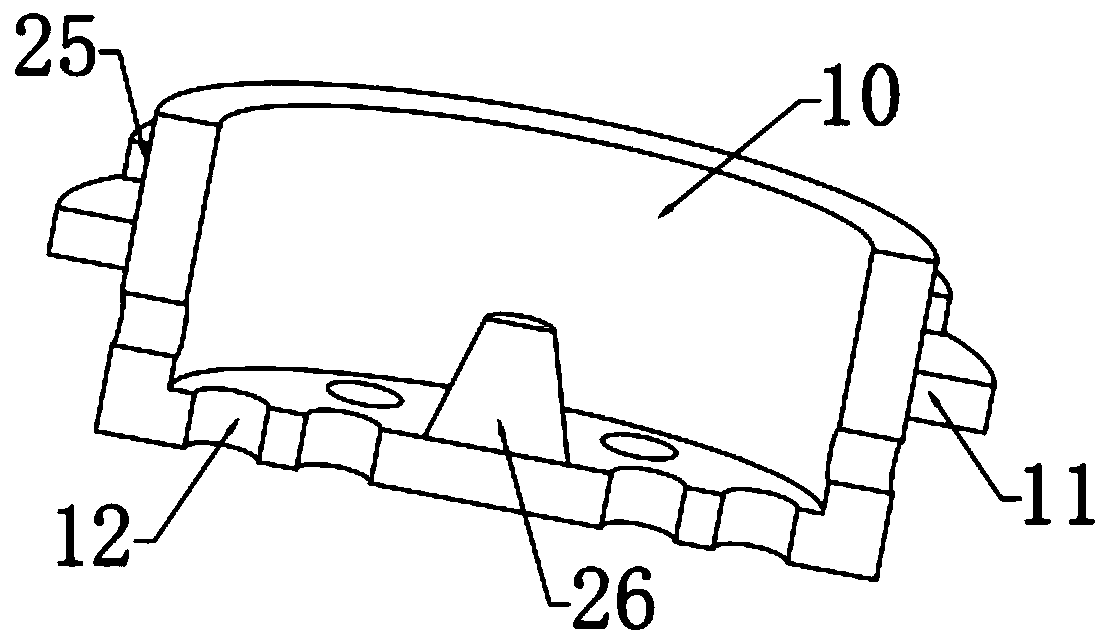
[0029] In this embodiment, the placement mechanism includes a placement tray 10, which is provided with a plurality of through holes 12 for feeding in and out of the plating solution, and the bottom of the inner side of the placement tray 10 is fixedly connected with a placement tray for placing pulleys. Block 26, the outer top of the placement tray 10 is fixedly connected with a turntable 11, the outer side of the turntable 11 is rotatably connected with a connecting block 17, the top of the connecting block 17 is hingedly provided with a connecting rod 19, and the other end of the connecting rod 19 Hinged with the slider 20, the slider 20 is slidably connected with the chute arranged at the...


PUM


Abstract

The invention relates to the technical field of automobile part machining, in particular to automobile belt pulley electroplating equipment. The automobile belt pulley electroplating equipment comprises an electroplating tank, supporting blocks are fixedly connected to the left side and the right side of the electroplating tank correspondingly, damping mechanisms are arranged at the bottoms of thesupporting blocks, fixing rods are fixedly connected to the tops of the supporting blocks, a top plate is fixedly connected to the tops of the fixing rods, a placement mechanism used for fixing a belt pulley is arranged on the lower side of the top plate, and the placement mechanism is connected with top plate through a lifting mechanism. According to the automobile belt pulley electroplating equipment, the placement mechanism is arranged, a first motor drives a driving gear to rotate, a placement disc can carry out rotation under the interaction of the driving gear and a driven gear, meanwhile, the placement disc can carry out vibration in an up and down mode through a vibration mechanism, and breaking and discharging water films and bubbles attached to blind holes and open holes can becarried out, so that electroplating is more comprehensive; and a damping mechanism is arranged, and the influence of vibration on the electroplating process can be avoided by utilizing multiple damping, so that the electroplating quality is advantageously improved.

Description

technical field [0001] The invention relates to the technical field of automobile parts processing, in particular to an electroplating equipment for automobile pulleys. Background technique [0002] The belt pulley belongs to the disc hub type parts, generally relatively large in size, and the manufacturing process is generally based on casting and forging (generally the larger size is designed by casting method, and the material is generally cast iron (good casting performance), very Use less cast steel (the casting performance of steel is not good); and the general size is smaller, it can be designed as forging, and the material is steel). Pulleys are mainly used for long-distance transmission of power, such as small diesel engine power output, agricultural vehicles, tractors, automobiles, mining machinery, machining equipment, textile machinery, packaging machinery, lathes, forging machines, and some small horsepower motorcycles. Transmission, transmission of agricultura...

Claims


Application Information

Patent Timeline
IPC IPC(8): C25D17/00C25D17/06C25D21/06C25D7/00C25D21/10
CPCC25D7/00C25D17/00C25D17/06C25D21/06C25D21/10
Inventor 钟国财
Owner 钟国财
Features
  • Generate Ideas
  • Intellectual Property
  • Life Sciences
  • Materials
  • Tech Scout
  • Unparalleled Data Quality
  • Higher Quality Content
  • 60% Fewer Hallucinations
Learn More