Wafer performance testing device and method

A technology of testing equipment and testing methods, which is applied in the direction of measuring equipment, single semiconductor device testing, electrical measurement, etc., and can solve the problems of low testing efficiency of testing equipment

Inactive Publication Date: 2020-08-21
QINGDAO GOERTEK MICROELECTRONICS RES INST CO LTD
View PDF9 Cites 4 Cited by
  • Summary
  • Abstract
  • Description
  • Claims
  • Application Information

AI Technical Summary

Problems solved by technology

[0003] The main purpose of the present invention is to provide a wafer performance testing device and

Method used


Image

  • Wafer performance testing device and method
  • Wafer performance testing device and method
  • Wafer performance testing device and method

Examples


Embodiment Construction

[0053] It should be understood that the specific embodiments described here are only used to explain the present invention, but not to limit the present invention.

[0054] The technical solutions in the embodiments of the present invention will be clearly and completely described below in conjunction with the accompanying drawings in the embodiments of the present invention. Obviously, the described embodiments are only a part of the embodiments of the present invention, rather than all the embodiments. Based on the embodiments of the present invention, all other embodiments obtained by those of ordinary skill in the art without creative work shall fall within the protection scope of the present invention.

[0055] It should be noted that all the directional indications (such as up, down, left, right, front, back...) in the embodiments of the present invention are only used to explain the difference between components in a specific posture (as shown in the accompanying drawings). ...


PUM


Abstract

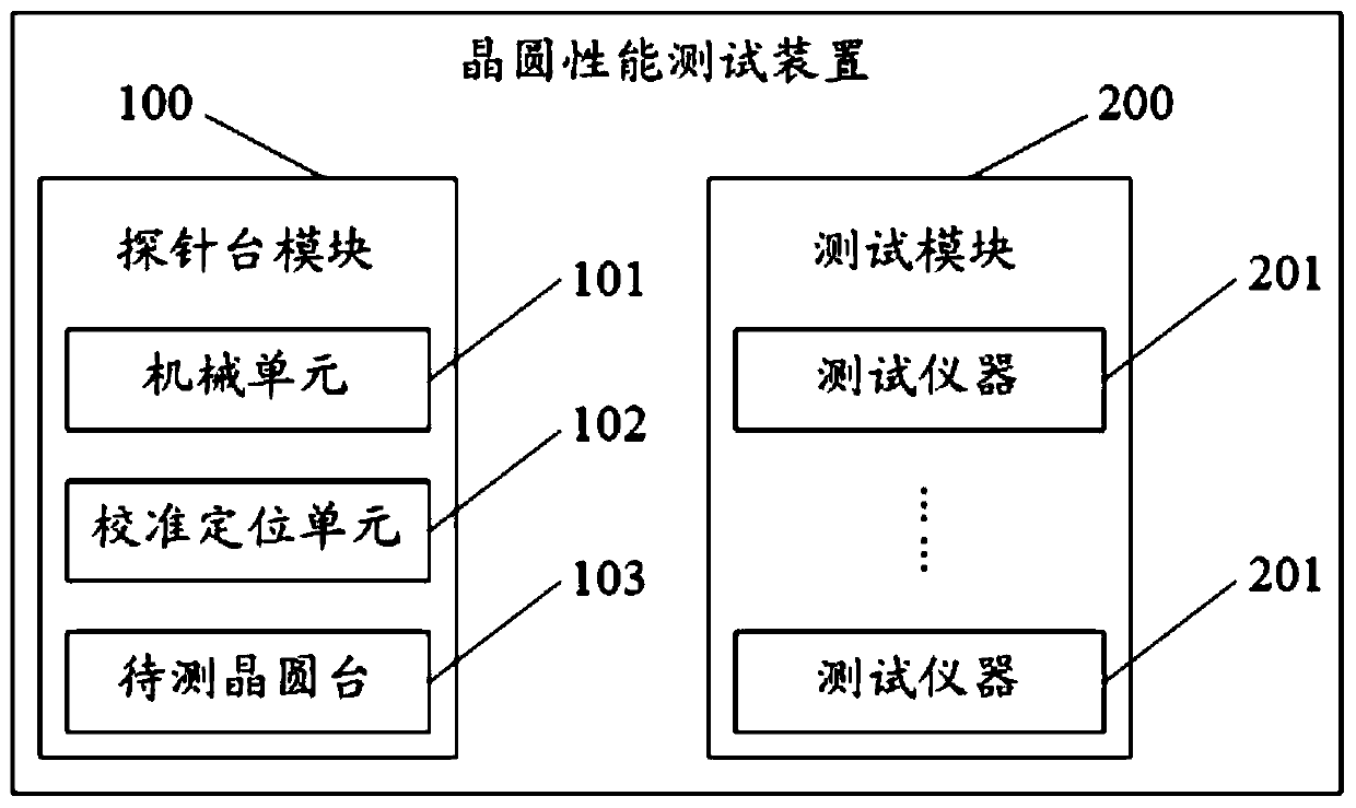
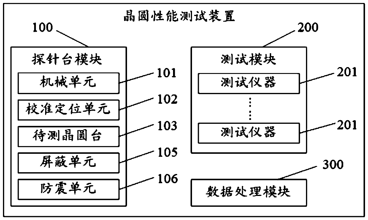
The invention relates to the technical field of semiconductor testing, in particular to a wafer performance testing device and method. The device comprises a probe station module and a test module. The probe station module comprises a mechanical unit and a calibration positioning unit. The probe station module comprises a wafer table to be tested; the mechanical unit transmits a plurality of single wafers to be tested to a wafer table to be tested by adopting different transmission tracks; the calibration positioning unit detects the current position information of each single wafer to be detected when the single wafer to be detected is located on the wafer table to be tested; when the current position information does not accord with preset position information, the position of each single wafer to be detected is adjusted; and the test module is used for carrying out performance testing on each single wafer to be tested according to the test trigger signal when the test trigger signalis received. The device comprises a plurality of feeding and discharging bins, a plurality of chip carriers can be placed in the feeding and discharging bins at the same time for feeding at the sametime, and a plurality of testing stations conduct testing in parallel, so that unnecessary repeated material feeding and discharging work is reduced, and the testing efficiency is improved.

Description

Technical field [0001] The invention relates to the technical field of semiconductor testing, in particular to a wafer performance testing device and method. Background technique [0002] At present, the MEMS (Micro-Electro-Mechanical System) microphone CV (Capacitance Voltage) test equipment currently in use in the industry is generally a two-station manual placement device and a separate wafer mapping (Wafer Mapping) Methods. The tested wafers are manually placed on the wafer table of the testing equipment one by one for testing. Each tested wafer is tested, and the tested wafer needs to be manually taken out and placed in the next tested wafer. This test method cannot be fully automated, wastes manpower and material resources, is slow, and affects productivity. Some test equipment tests a lot (Lot) of tested wafers placed on a carrier at a time. After the test is completed one batch, the carrier is replaced to check the next batch of tested wafers. carry out testing. Repla...

Claims


Application Information

Patent Timeline
IPC IPC(8): G01R31/26G01R31/01
CPCG01R31/2601
Inventor 宋友奎于上家
Owner QINGDAO GOERTEK MICROELECTRONICS RES INST CO LTD
Why Eureka
Try Eureka