
Laser radar device and receiving module thereof

A laser radar and receiving module technology, applied in the field of radar detection, can solve the problems of low detection accuracy, unfavorable installation and adjustment, and large space occupied by laser radar equipment, so as to increase detection accuracy, improve detection accuracy, and reduce overall volume Effect

Pending Publication Date: 2020-08-21
NINGBO SUNNY AUTOMOTIVE OPTECH
View PDF4 Cites 0 Cited by
  • Summary
  • Abstract
  • Description
  • Claims
  • Application Information

AI Technical Summary

Problems solved by technology

Therefore, the number and size of mirrors seriously affects the manufacturing cost of prior art LiDAR devices
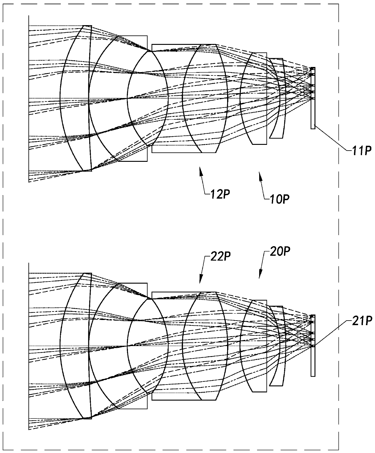
The way that the receiving end 20P and the transmitting end 10P work independently also makes the lidar equipment occupy a large space, which is not conducive to miniaturization, and it is difficult to apply to small equipment to perform detection tasks
In addition, the number of lenses and the size of the lenses in the prior art laser radar equipment have seriously affected the production cost of the overall laser radar system, which is not conducive to assembly and adjustment.
[0005] The transmitting end 10P and the receiving end 20P of this laser radar device in the prior art form two sets of different optical systems, which will inevitably cause the optical path of the light emitted by the laser light source 11P to be different from the optical path of the light received by the sensor 22P, which is not conducive to the The sensor 22P receives light in a specific area, which affects the detection accuracy of the lidar system
[0006] In addition, the sensor 21P of the receiving end 20P of the laser radar is usually a single APD detector, and the detection area of ​​the receiving end 20P in the horizontal and vertical directions is limited by the receiving lens 22P, and it is difficult to change the detection field of view.
In general, the sensor 21P of the receiving end 20P can receive light in a specific direction and a specific angle, and the detection accuracy of detection targets in other directions and angles is low, thus limiting the overall positioning accuracy of the lidar

Method used


Image

  • Laser radar device and receiving module thereof
  • Laser radar device and receiving module thereof
  • Laser radar device and receiving module thereof

Examples


Embodiment Construction

[0088] The following description serves to disclose the present invention to enable those skilled in the art to carry out the present invention. The preferred embodiments described below are only examples, and those skilled in the art can devise other obvious variations. The basic principles of the present invention defined in the following description can be applied to other embodiments, variations, improvements, equivalents and other technical solutions without departing from the spirit and scope of the present invention.

[0089]Those skilled in the art should understand that in the disclosure of the present invention, the terms "vertical", "transverse", "upper", "lower", "front", "rear", "left", "right", " The orientation or positional relationship indicated by "vertical", "horizontal", "top", "bottom", "inner", "outer", etc. is based on the orientation or positional relationship shown in the drawings, which are only for the convenience of describing the present invention ...


PUM


Abstract

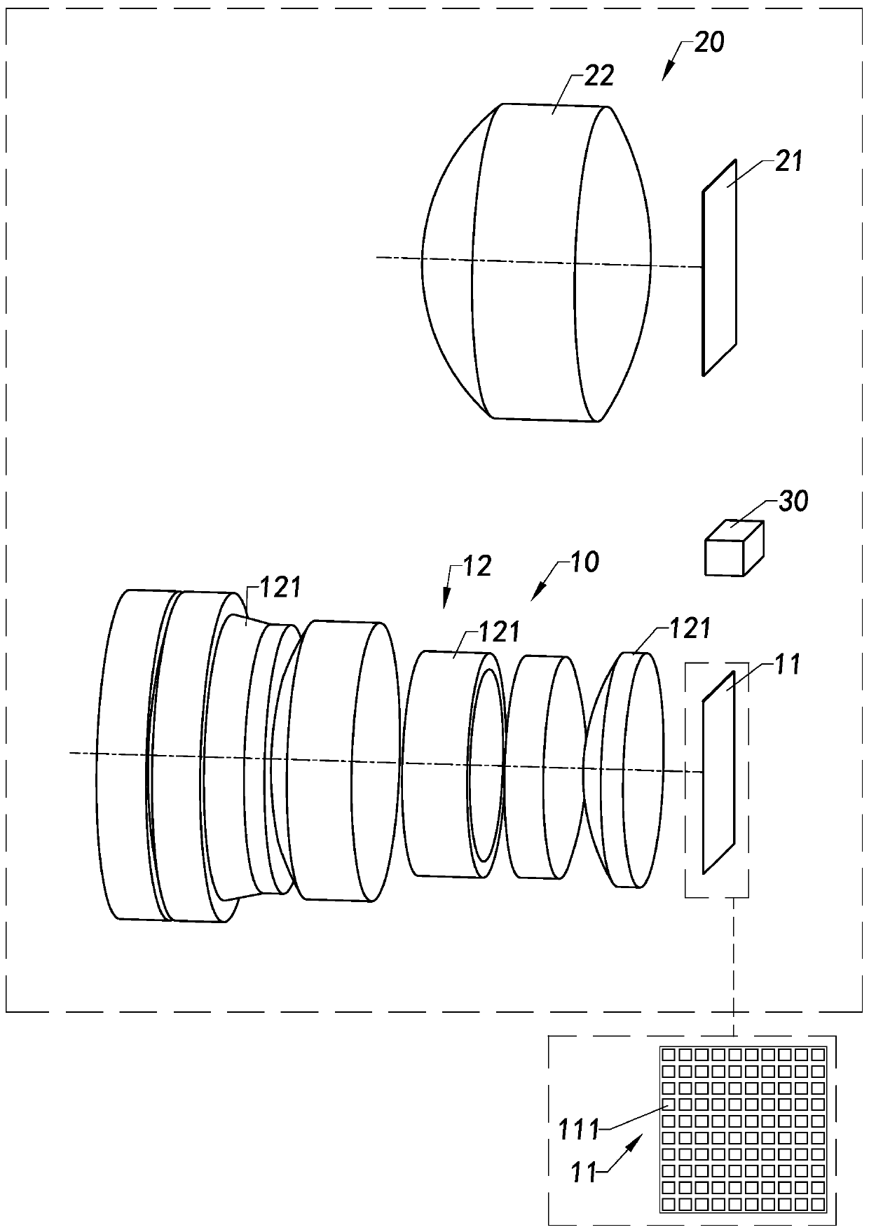
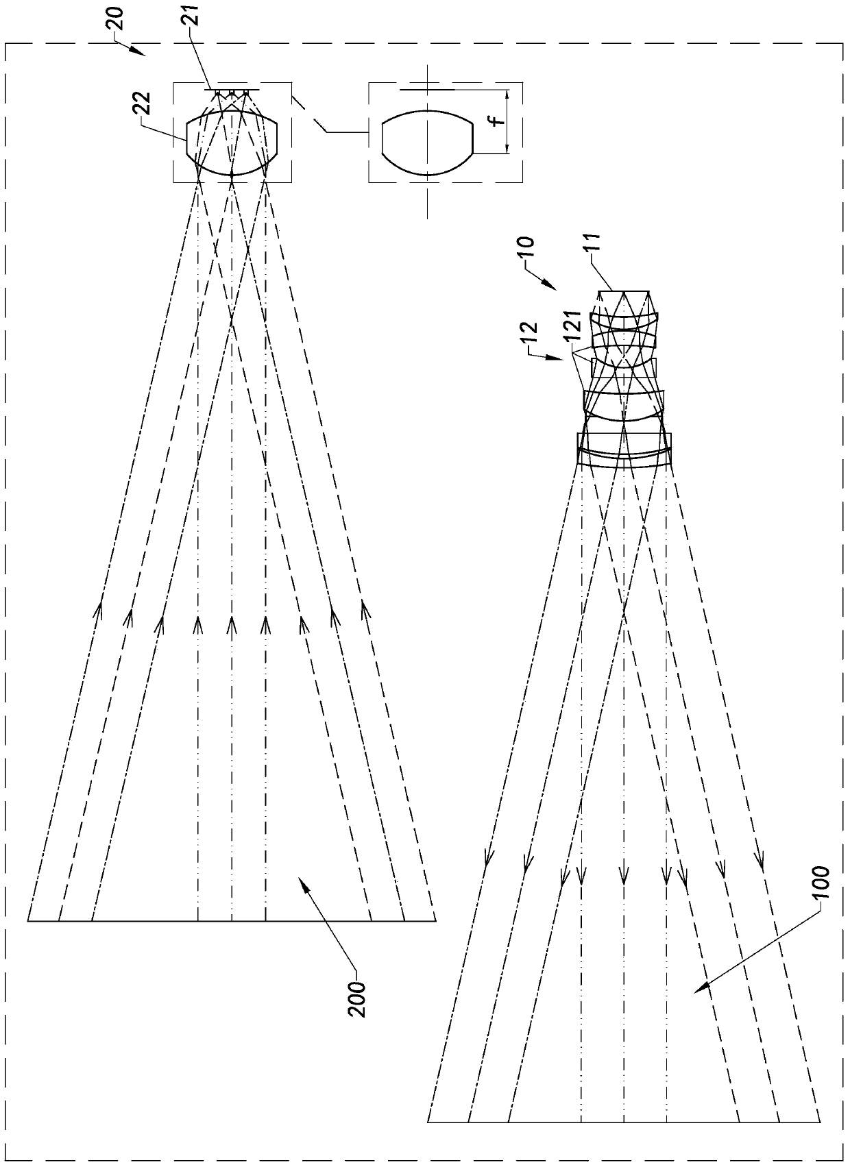
The invention provides a laser radar device and a receiving module thereof. The laser radar device comprises a transmitting module, a receiving module and a processor, wherein the transmitting moduletransmits laser light, the receiving module is used for receiving the reflected laser light, the receiving module comprises at least one detector device and a lens, the lens shapes the laser light tothe detector device, the lens is a single-chip lens, and the processor obtains detection information based on the laser light received by the receiving module.

Description

technical field [0001] The invention relates to the field of radar detection, in particular to a laser radar device and a receiving module thereof. Background technique [0002] Lidar is a radar system that emits laser beams to detect the position, speed and other characteristic quantities of the target. Its working principle is to transmit a detection signal (laser beam) to the target, and then receive the signal reflected from the target (target echo) ) is compared with the transmitted signal, and after proper processing, the relevant information of the target can be obtained and the target can be detected. [0003] The laser transmitting end and the laser receiving end of the prior art lidar are separated, so two multi-chip lenses are required to transmit and receive light energy in a certain angle range respectively. Refer to the attached figure 1 As shown, a radar device in the prior art is disclosed, wherein the radar device includes a transmitting end 10P and a rece...

Claims


Application Information

Patent Timeline
Patent Type & Authority Applications(China)
IPC IPC(8): G01S7/481G01S17/06G01S17/58
CPCG01S7/4811G01S7/4816G01S17/06G01S17/58
Inventor 张俊明徐超杨佳曹艳亭
Owner NINGBO SUNNY AUTOMOTIVE OPTECH
Learn More