Eureka AIR delivers breakthrough ideas for toughest innovation challenges, trusted by R&D personnel around the world.

High-heat-conduction air cooling rack of electronic equipment

A technology for electronic equipment and air-cooled machines, which is applied in the construction parts of electrical equipment, electrical components, cooling/ventilation/heating transformation, etc., which can solve the problem of limiting the range of use of air-cooling racks, increasing volume and weight, and not being able to meet the needs of aircraft space and weight requirements to achieve the effect of increasing the conduction heat dissipation area, improving adaptability and reliability, and simple structure

Pending Publication Date: 2020-08-21
10TH RES INST OF CETC
View PDF4 Cites 2 Cited by
  • Summary
  • Abstract
  • Description
  • Claims
  • Application Information

AI Technical Summary

Problems solved by technology

[0006] The above methods all have great limitations, and they are all solved at the cost of increasing volume and weight. They often cannot meet the extremely strict space and weight requirements on the aircraft, which greatly limits the scope of use of air-cooled racks.

Method used


Image

  • High-heat-conduction air cooling rack of electronic equipment
  • High-heat-conduction air cooling rack of electronic equipment
  • High-heat-conduction air cooling rack of electronic equipment

Examples


Embodiment Construction

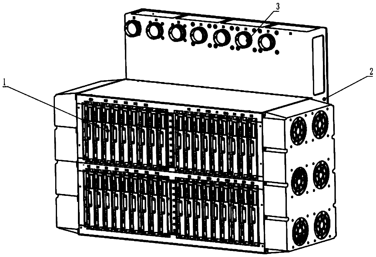
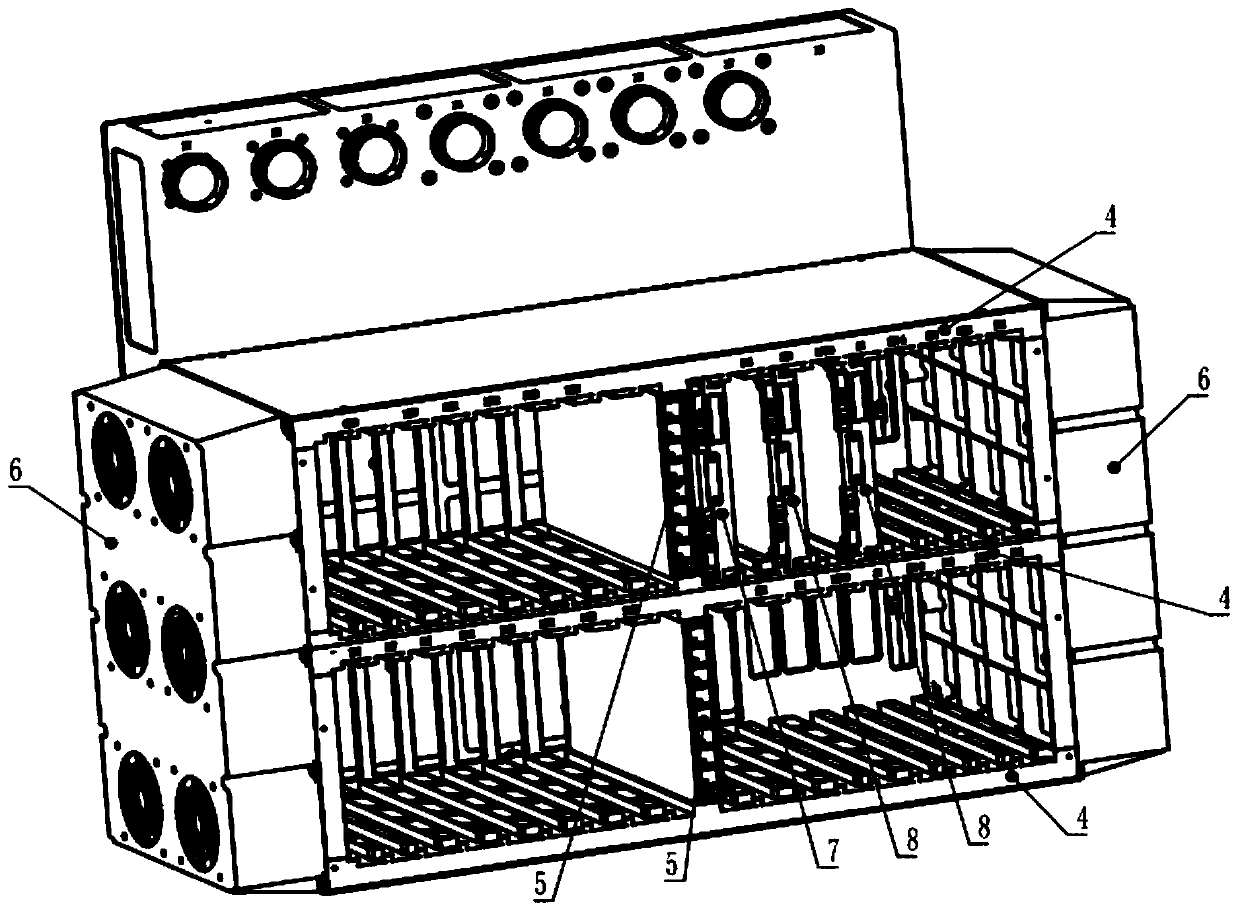
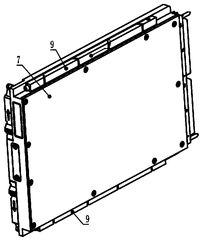
[0019] refer to Figure 1-Figure 5 . In the preferred embodiment described below, a high thermal conductivity air-cooled rack for electronic equipment includes: a rack that is divided into three functional areas: a module carrying area 1, a backplane carrying area 2, and an external interface area 3 according to different functions The structure is characterized in that: the backplane carrying area 2 is provided with external interfaces arranged in a line array, and the middle part of the module carrying area 1 in the heat-conducting air-cooled rack is provided with a movable air-cooled partition 5 connected to the upper and lower compartments, and the heat-conducting air Each module carrying area 1 in the cold rack has a high heat consumption module 7 and an ordinary air-cooled module 8 installed in the rack guide rail groove through a wedge-shaped locking strip. The side of the entire module is attached to the outer surface of the left side of the deflector 10, and the heat...


PUM


Abstract

The invention discloses a high-heat-conduction air cooling rack for electronic equipment, wherein the high-thermal-conductivity air cooling rack is mainly used for aviation and communication electronic equipment. According to the technical scheme, movable air cooling partition plates connected up and down at interval layer are arranged in the middle of a module bearing area in a heat conduction air cooling rack; each module bearing area is internally provided with a high heat consumption module and a common air cooling module which are arranged in rack guide rail grooves through wedge-shaped locking strips; the side face of the whole high heat consumption module is attached to the outer surface of the left side of a flow guide plate through the pressure of the wedge-shaped locking strip, the generated heat is conducted to the movable air cooling partition plate through the surface of the module body, and cold air is taken away through an air duct; a working fluid generated by air cooler assemblies on the two sides of the box body of the rack enters each module bearing area from the movable air cooling partition plates in opposite directions to establish a smooth air duct, cold airenters from the middle of the movable air cooling partition plate, air flow is conducted in the air ducts, and air closed circulation is conducted in the air ducts of the rack air cooling partition plate, so that heat of the high heat consumption module and / or the air cooling module is taken away.

Description

technical field [0001] The invention relates to a high heat conduction air-cooled rack mainly used for aviation and communication electronic equipment. Background technique [0002] Electronic equipment usually requires high reliability, and excellent heat dissipation is an important guarantee for the reliable operation of electronic equipment. In electronic equipment, the main heat generation is generated by high-power devices, so the heat dissipation of high-power devices is the key to the heat dissipation of the entire electronic equipment. Due to the widespread use of multi-layer circuit boards and high-density surface mount components in electronic equipment, electronic components and equipment will dissipate a lot of heat during operation, and the heat flux will increase. In order to ensure the reliability of components and communication equipment, it is necessary Proper thermal design of electronic equipment. The electronic equipment that realizes system functions m...

Claims


Application Information

Patent Timeline
Patent Type & Authority Applications(China)
IPC IPC(8): H05K7/20
CPCH05K7/20172H05K7/20145
Inventor 管志宏刘正伟杨德春黄贤浪
Owner 10TH RES INST OF CETC
Why Eureka
Eureka Blog
Learn More