Tamping assembly for a track-tamping machine

A technology of tamping machine and unit, applied in the direction of track, track superstructure, road, etc., can solve the problems of shortened life and difficult to maintain hydraulic bolt seal for a long time, and achieve the effect of reducing error proneness

Inactive Publication Date: 2020-08-21
HP3 REAL GMBH
View PDF14 Cites 1 Cited by
  • Summary
  • Abstract
  • Description
  • Claims
  • Application Information

AI Technical Summary

Problems solved by technology

This leads to reduced life and difficulty in durably maintaining the seal of hydraulic bolted joints

Method used


Image

  • Tamping assembly for a track-tamping machine
  • Tamping assembly for a track-tamping machine
  • Tamping assembly for a track-tamping machine

Examples


Embodiment Construction

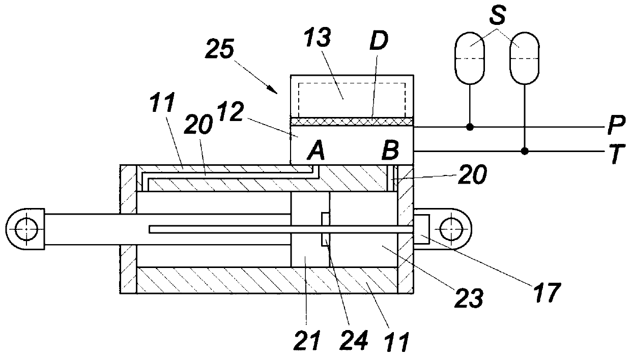
[0017] figure 1 A fully hydraulic linear tamping drive is shown. The hydraulic cylinder 11 has a bore embedded in the cylinder block, which serves as a hydraulic input 20 and is supplied directly via the ports A, B by an attached valve 25 . Hydraulic fluid under pressure from the hydraulic pump is fed into the control valve 25 via the hydraulic pressure feed line P, which is led back to the hydraulic tank via the tank return line T. As in the tank return line T, a hydraulic accumulator S is likewise arranged in the hydraulic pressure supply line P to the mechanical cylinder control valve part 12 .

[0018] A stroke sensor 17 is integrated in the hydraulic cylinder 11 . An embodiment is shown here as an inductive distance sensor, in which a position magnet 24 is provided, by means of which the deflection of the piston 21 is measured. If the cylinder chamber 23 is brought to pressure P via port B, the piston moves to the left. If the pressure loading on the piston is switche...


PUM


Abstract

Tamping assembly (1) for a track-tamping machine having tamping tool pairs (3) which take the form of oscillating levers and are arranged on a carrier (7) guided height-adjustably in a tamping assembly frame and of which the lower tamping tine ends (10), intended for engagement in a ballast bed (4), can be driven by an oscillatory drive (11) and can be adjusted hydraulically with respect to one another, wherein each of the tamping tools (3) of a tamping tool pair is assigned a hydraulic cylinder (11) and, where appropriate, a displacement sensor (7) for determining the hydraulic cylinder position, and the hydraulic cylinders (11) form both the linear adjusting drive and the oscillatory drive of the tamping tools (3), and wherein, to activate the hydraulic cylinders (11), electrohydraulic valves are provided which comprise a mechanical hydraulic-cylinder activating valve part (12) and associated valve electronics (13). To provide advantageous construction conditions, it is proposed thatthe valve electronics (13) are mounted in an oscillation-damped manner with respect to the hydraulic cylinder (11) and / or the mechanical hydraulic-cylinder activating valve part (12).

Description

technical field [0001] The invention relates to a tamping unit for a rail tamping machine, the tamping unit having a pair of tamping tools designed as vibrating rods arranged on a support that can be height-adjustable within the frame of the tamping unit Adjustably guided, the lower tamper pick ends of the pair of tamping tools for insertion into the gravel bed can be driven by an oscillating drive and can be hydraulically advanced relative to each other, wherein each of the pair of tamping tools Each tamping tool is equipped with a hydraulic cylinder and a stroke sensor for determining the position of the hydraulic cylinder if necessary, and the hydraulic cylinder forms a linear feed drive and an oscillating drive for the tamping tool, and wherein, for controlling the hydraulic cylinder, there is An electrohydraulic valve comprising a mechanical cylinder control valve part and associated valve electronics. Background technique [0002] The tamping unit penetrates the balla...

Claims


Application Information

Patent Timeline
Patent Type & Authority Applications(China)
IPC IPC(8): E01B27/16
CPCE01B27/16E01B2203/12B07C5/368
Inventor B.利赫特伯格
Owner HP3 REAL GMBH
Why Eureka
Try Eureka