Method for producing a wave spring washer for a centrifugal pendulum device, centrifugal pendulum device, clutch disc; and powertrain

A technology of centrifugal force pendulum and wave spring, applied in the direction of springs/shock absorbers, springs, manufacturing tools, etc., can solve the problem of expensive manufacturing of spring discs, and achieve the effect of effective mass production

Active Publication Date: 2020-08-21
SCHAEFFLER TECH AG & CO KG
View PDF9 Cites 0 Cited by
  • Summary
  • Abstract
  • Description
  • Claims
  • Application Information

AI Technical Summary

Problems solved by technology

[0004] However, a disadvantage of the spring disks used by the prior art has

Method used


Image

  • Method for producing a wave spring washer for a centrifugal pendulum device, centrifugal pendulum device, clutch disc; and powertrain
  • Method for producing a wave spring washer for a centrifugal pendulum device, centrifugal pendulum device, clutch disc; and powertrain
  • Method for producing a wave spring washer for a centrifugal pendulum device, centrifugal pendulum device, clutch disc; and powertrain

Examples


Embodiment approach 1

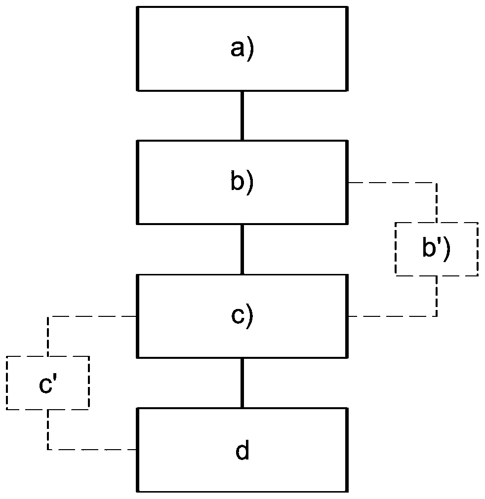
[0051] The manufacturing method for manufacturing the spring disk 7 is carried out (completely) by the following steps: a) providing the sheet material blank as a hardened sheet material ( / providing the sheet material blank from hardened metal); b) forming the annular workpiece (also called In the case of blanks), the contours 9a, 9b are punched or laser cut; c) the workpiece is cold-formed in a closed forming tool; and d) the workpiece is stress-relieving annealed.

[0052] In other words, in embodiment 1, therefore firstly a hardened sheet metal strip (sheet material blank) is provided, usually rolled up into a coil (step a)). Then (in step b) the desired contour 9a, 9b of the corrugated disk 7 is produced from the strip by means of punching in one or more strokes or by means of laser cutting. The slab is then cold-formed in a closed tool (forming tool) in one or more forming steps into a fully established corrugated disc 7 (step c)). Subsequently, stress relief annealing (...

Embodiment approach 2

[0054] The manufacturing method for manufacturing the spring disk 7 is carried out (completely) by the following steps: a) providing the sheet material blank as a hardened sheet material ( / providing the sheet material blank from hardened metal); b) forming the annular workpiece (also called stamping or laser cutting of the profiles 9a, 9b in the case of a slab); b') heating the slab to a suitable forming temperature in an oven (outside the closed forming tool) or in a closed forming tool; c ) hot forming said slab in a closed forming tool; and d) stress relief annealing the workpiece.

[0055] In other words, in embodiment 2, a hardened sheet metal strip (sheet blank) is therefore firstly provided, usually rolled up into a coil. Then (in step b)) the desired contour 9a, 9b of the corrugated disk 7 is produced from the strip by means of punching in one or more strokes or by means of laser cutting. Then (in step b')) the slab is heated in a furnace to a suitable forming tempera...

Embodiment approach 3

[0057] The manufacturing method for manufacturing the spring disk 7 is carried out (completely) by the following steps: a) providing the sheet blank as an unhardened sheet ( / providing the sheet blank from unhardened metal); The profile 9a, 9b is stamped or laser cut in the case of a slab); c) the slab is cold formed in a closed forming tool; c') the workpiece is hardened by means of a suitable hardening process; and d) stress relief annealing the workpiece.

[0058] In other words, in embodiment 3, an unhardened sheet metal strip (sheet material blank) is therefore first provided, usually rolled up into a coil. Then (in step b)) the desired contour 9a, 9b of the corrugated disk 7 is produced from the strip by means of punching in one or more strokes or by means of laser cutting. The slab is then cold-formed (in step c) in a closed tool (forming tool) in one or more forming steps into a fully established corrugated disk 7 . Next, the corrugated disk 7 is hardened (step c')) u...


PUM


Abstract

The invention relates to a method for producing a wave spring washer (7) for a centrifugal pendulum device (1), having the following steps: a) providing a sheet metal blank, b) forming a contour (9a,9b) of the spring washer (7) to be produced from the sheet metal blank, thereby producing a workpiece, c) reshaping the workpiece in a closed reshaping tool such that a wave spring region (12) of thespring washer (7) is produced, and d) stress-relief annealing the workpiece, thereby forming the spring washer (7). The invention additionally relates to a centrifugal pendulum device (1) comprising aspring washer (7) which is produced using the aforementioned method, and to a clutch disc (10) and a powertrain comprising a respective centrifugal pendulum device (1).

Description

technical field [0001] The invention relates to a method for producing a wave spring disk for a centrifugal pendulum device (also called centrifugal pendulum for short). The invention also relates to a centrifugal pendulum device for a drive train of a motor vehicle, such as a passenger car, bus, truck or other commercial vehicle, which has a support that can rotate about an axis of rotation, A pendulum mass, a contact element which bears against the pendulum mass in a relatively displaceable manner, and a wave-spring disk (also called a corrugated disk) produced according to the method described, said pendulum mass is pivotable along a sliding track Received on the bracket in such a way that during operation a return moment against rotational inhomogeneities is generated by the pendulum mass, the wave-shaped spring disk presses the contact element onto the pendulum mass in the axial direction of the axis of rotation, wherein the spring disk The fastening area is connected to...

Claims


Application Information

Patent Timeline
IPC IPC(8): F16F15/14F16F1/32
CPCF16F1/328F16F15/145C21D9/02
Inventor T·弗里奇J·马特斯E·弗朗茨A·鲁施M·黑斯勒M·凯斯勒L·索瑞特G·屈恩E·迈尔C·迈尔
Owner SCHAEFFLER TECH AG & CO KG
Why Eureka
Try Eureka