Beam shaper

Inactive Publication Date: 2007-12-11
MODILIS HLDG LLC
View PDF20 Cites 23 Cited by
  • Summary
  • Abstract
  • Description
  • Claims
  • Application Information

AI Technical Summary

Benefits of technology

[0006]It is an object for a beam shaper of the invention to provide a decisive improvement regarding the above-described technology and, hence, to raise essentially the technical level of prior art. In order to fulfill this object, a beam shaper of the invention is principally characterized in that its transmission element guiding the light beam/beams has

Problems solved by technology

In this context, however, no solutions have been describ

Method used


Image

  • Beam shaper
  • Beam shaper
  • Beam shaper

Examples


Embodiment Construction

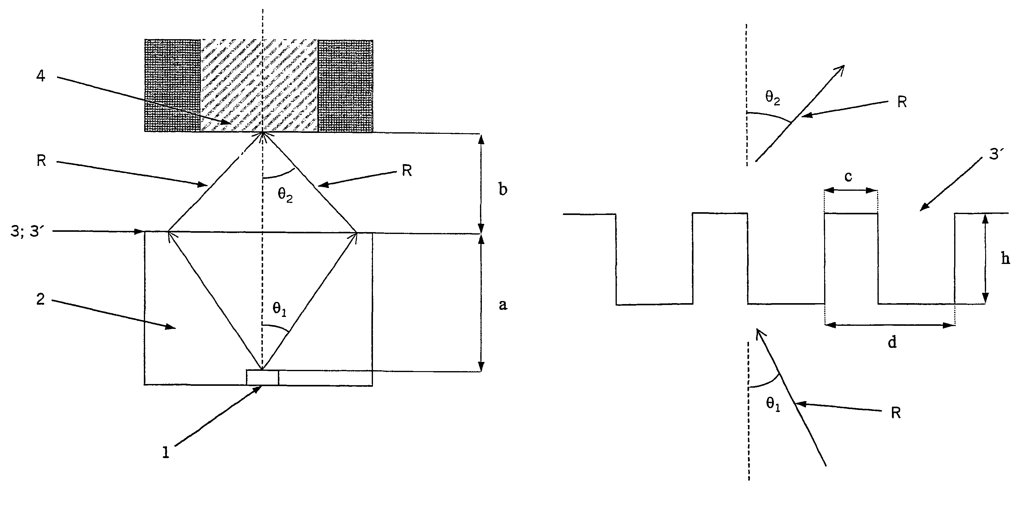
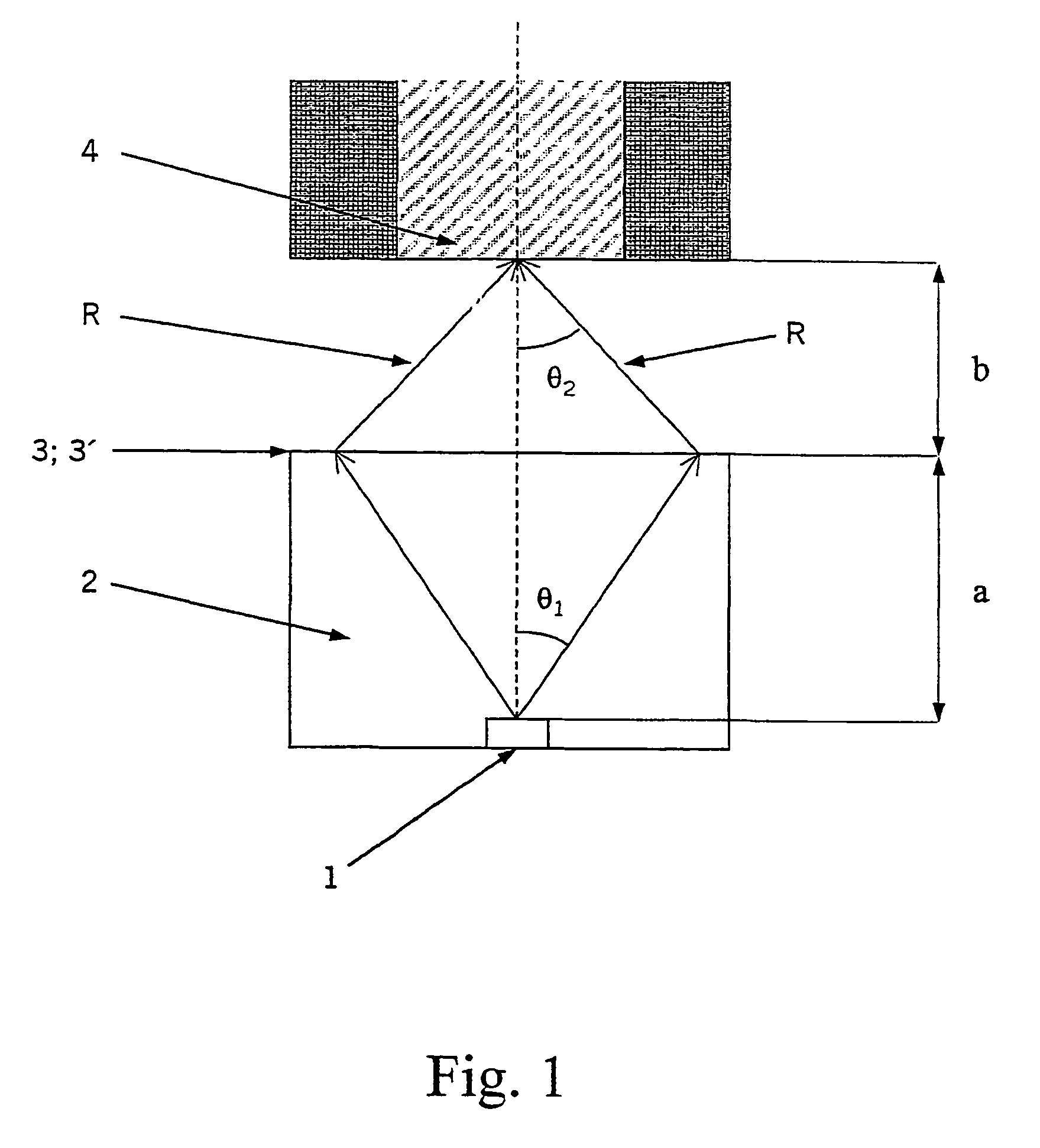
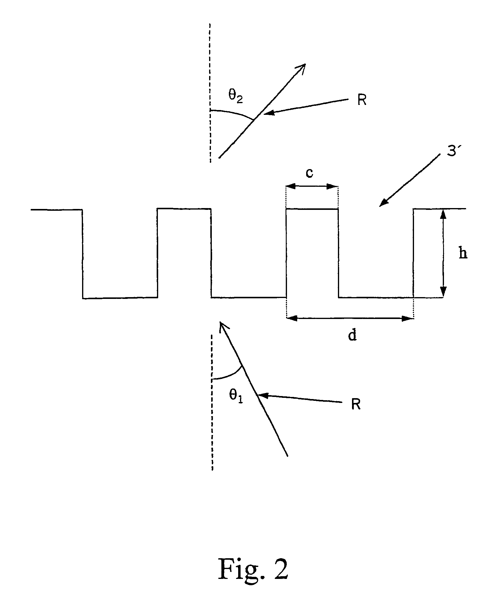
[0011]The invention relates to a beam shaper, which is intended for use in connection with a quasi-monochromatic light source 1 and which is fabricated from a substantially transparent material as a transmission element 3 guiding the propagation of light for rounding, making elliptical, collimating, diverging, converging and / or for the like application of a light beam / beams R. The transmission element 3; 3′ of a beam shaper guiding the light beam / beams R has a structure which at least partially consists of binary, surface relief type of diffractive patterns, having local grating periods thereof optimized with respect to longitudinal and transverse directions, as well as with respect to an optical axis, essentially in accordance with the Bragg diffraction geometry for providing a maximum diffraction efficiency.

[0012]The following description deals with the basic inventive concepts by explaining the Bragg effect with reference to the accompanying FIGS. 1-5. FIG. 1 depicts a purely dif...


PUM


Abstract

A beam shaper intended for use in connection with a quasi-monochromatic light source and which is fabricated from a substantially transparent material as a transmission element guiding the propagation of light for rounding, making elliptical, collimating, diverging, converging and/or for the like application of a light beam/beams. The beam shaper has its transmission element guiding the light beam/beams provided with a structure which at least partially consists of binary, surface relief type of diffractive patterns, having local granting periods thereof optimized with respect to longitudinal and transverse directions, as well as with respect to an optical axis, essentially in accordance with the Bragg diffraction geaometry for providing a maximum diffraction efficiency.

Description

CROSS-REFERENCE TO RELATED APPLICATIONS[0001]This application claims priority to Finnish patent application 20002737 filed 13 Dec. 2000 and is the national phase of PCT / FI01 / 01082 filed 11 Dec. 2001.FIELD OF THE INVENTION[0002]The invention relates to a beam shaper, which is intended for use in connection with a quasi-monochromatic light source and which is fabricated from a substantially transparent material as a transmission element guiding the propagation of light for rounding, making elliptical, collimating, diverging, converging and / or for the like application of a light beam / beams.[0003]For the above application there are presently known transmission elements e.g. as follows: a) refractive lens systems, b) diffractive lens systems, and c) hybrid assemblies.[0004]In addition to the foregoing, use is currently made also of a so-called Bragg reflector, the assembly used in this context being partially reflective and partially transparent. It is further known to employ the Bragg c...

Claims


Application Information

Patent Timeline
IPC IPC(8): G02B5/18G02B1/00G02B27/09H01L51/50H05B33/02
CPCG02B5/1866Y10S362/80G02B5/18
Inventor HATJASALO, LEORINKO, KARI
Owner MODILIS HLDG LLC
Why Eureka
Try Eureka