Wavelength-tunable spectrometer and wavelength tuning method thereof

a spectrometer and wavelength tuning technology, applied in the direction of optical radiation measurement, instruments, spectrometry/spectrophotometry/monochromators, etc., can solve the problems of high cost, low precision, increase of spectrometer size, etc., and achieve optimal efficiency, high degree of design freedom, and optimal diffraction efficiency

Inactive Publication Date: 2012-01-05
NANOBASE
View PDF5 Cites 8 Cited by
  • Summary
  • Abstract
  • Description
  • Claims
  • Application Information

AI Technical Summary

Benefits of technology

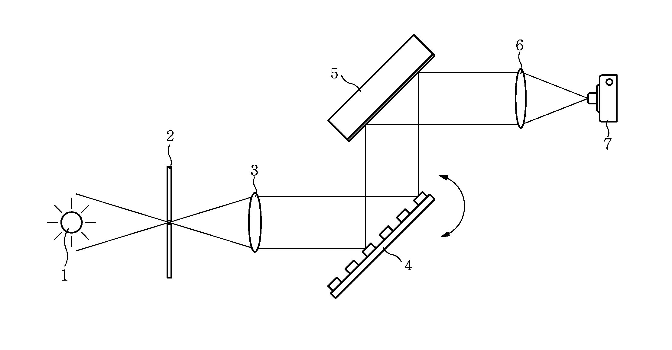
[0026]According to embodiments of the present invention, since a spectrum of incident light can be obtained with the optimal diffraction efficiency based on a wavelength of the incident light without motion of a camera for observation and replacement of a diffractor by rotatably arranging a transmission type diffractor to provide an incidence angle to provide the optimal efficiency for a selected wavelength of an external light source to be observed and arranging a mirror to provide light, which is changed in its diffraction angle depending on rotation of the transmission type diffractor and the wavelength of the incident light, on the same output light path irrespective of a change in the rotation of the transmission type diffractor and the wavelength of the incident light, it is possible to reduce a size of the spectrometer, product cost and possibility of failure.
[0027]In addition, since a diffraction grid arrangement angle of a transmission type diffractor can be selected to allow a design of a desired optical path with the optimal efficiency maintained, it is possible to achieve a high degree of freedom of design for a spectrometer and reduced volume of the spectrometer.
[0028]In addition, since diffraction efficiency of incident light selected from a wide band of wavelengths can be set to the maximum diffraction efficiency by integrating a transmission type diffractor and a mirror and by using only single angle adjustment thereof based on a wavelength of the incident light, it is possible to analyze incident light with the optimal diffraction efficiency without separate connection or manipulation.
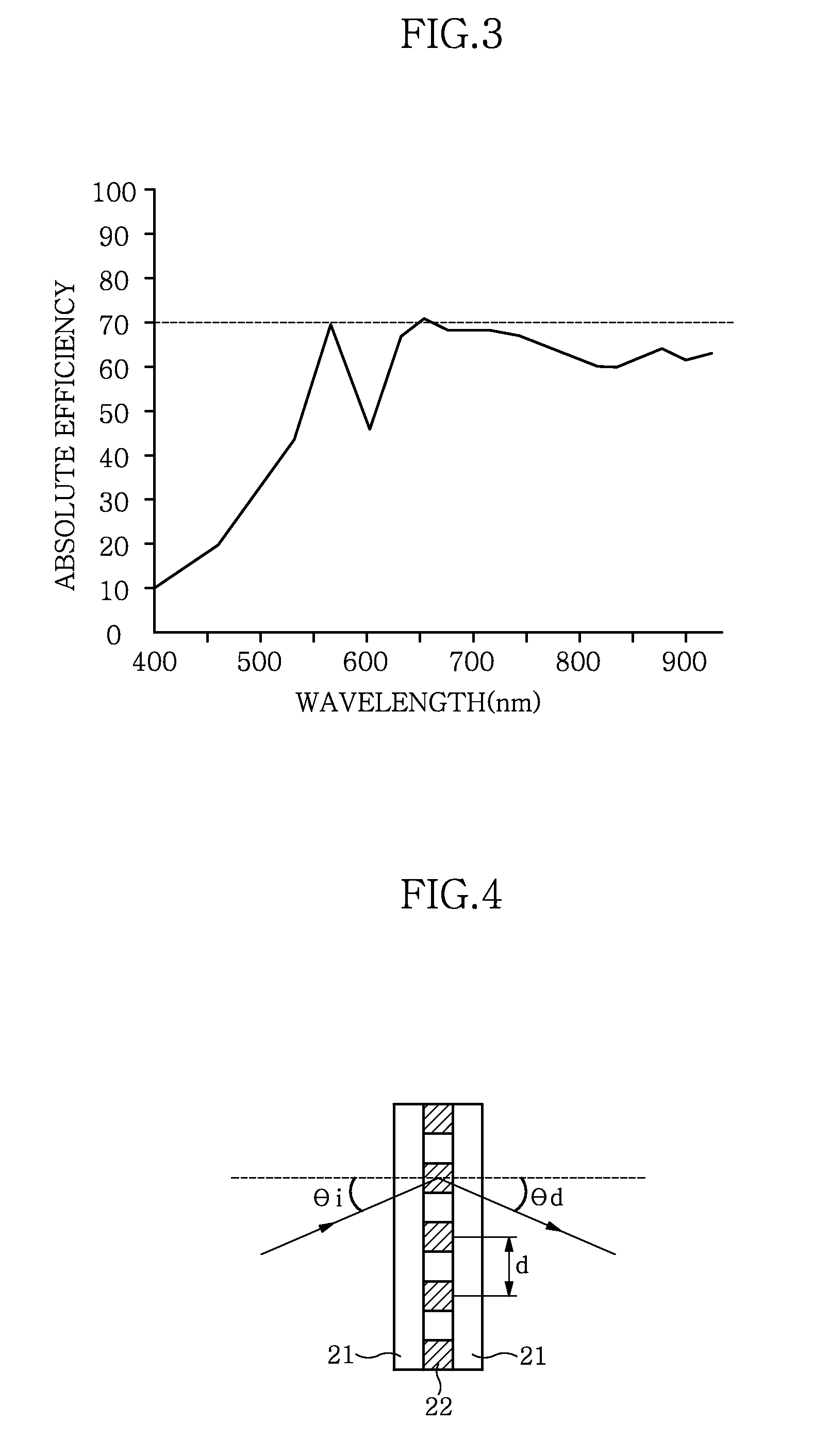
[0029]In addition, a volume phase holographic grating can be coupled to a mirror at a fixed angle such that a diffraction angle of transmitted light becomes the maximum efficiency angle and the light is converged onto a fixed output light path in consideration of an incidence angle of light incident into the volume phase holographic grating with high transmission efficiency over a wide band of wavelengths and a diffraction grid arrangement angle, it is possible to reduce size and number of operation units, product costs and a volume of the system, and increase efficiency and precision of the system.
[0030]It is particularly noted that the present invention has the effect of maintaining the highest precise spectrum analysis of incident light by diffracting light having a selected wavelength with the optimal diffraction efficiency, instead of selecting a particular wavelength from a light source having a plurality of different wavelengths, which is different from the effect of generating a precise short wavelength light source.

Problems solved by technology

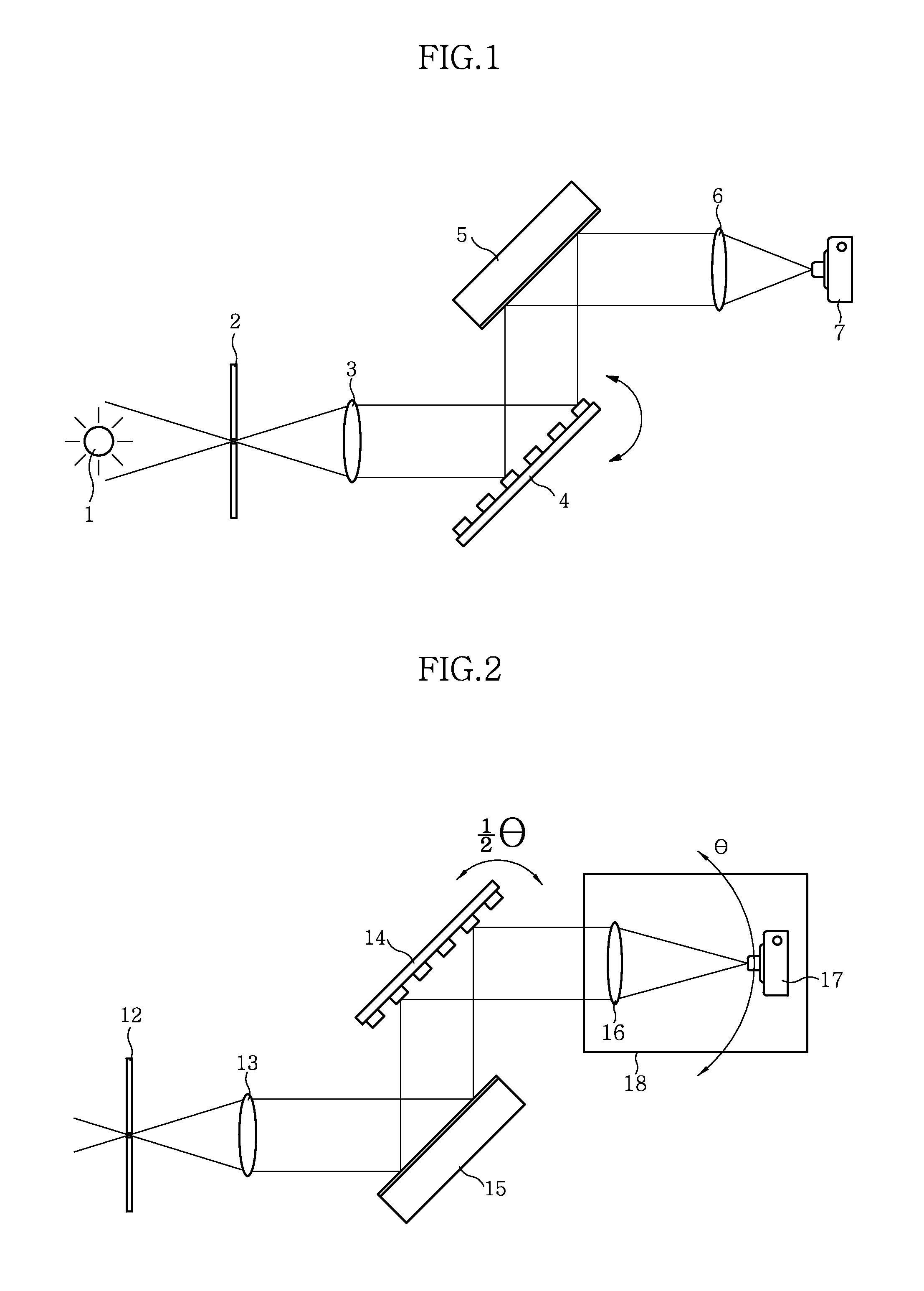
Although this configuration has a good optical characteristic, this configuration is rarely used since the camera 17, which is large-sized and specialized for the spectrometer, and the condensing lens 16 have to rotate over a wide region, which results in increase of size of the spectrometer, high costs, and low precision due to abrasion by physical driving.
In recent years, researches on wavelength tuning using a transmission type diffractor instead of the reflection type diffractor have been progressed; however, configuration using such a transmission type diffractor still has a problem of large size and high cost since it also uses the configuration shown in FIG. 2.

Method used


Image

  • Wavelength-tunable spectrometer and wavelength tuning method thereof
  • Wavelength-tunable spectrometer and wavelength tuning method thereof
  • Wavelength-tunable spectrometer and wavelength tuning method thereof

Examples


Embodiment Construction

[0042]The present invention relates to a novel configuration and an application of operation principle based on Korean Patent Application No. 10-2008-0005828, titled “wavelength tuning apparatus and method,” owned by the applicant. This patent application relates to a wavelength tunable laser which selects and resonates a particular wavelength of input laser light having a plurality of different wavelengths and outputs light having the selected wavelength precisely. However, it is noted that the present invention relates to a spectrometer which analyzes a spectrum of input light having a particular wavelength to detect properties of material transmitting the input light or material generating the particular wavelength, and more particularly, to a wavelength tunable spectrometer and wavelength tuning method which is capable of diffracting input light having a wavelength selected from a wide band of wavelengths with the highest diffraction efficiency irrespective of the selected wavel...


PUM


Abstract

This invention relates to a wavelength tunable spectrometer and a wavelength tuning method thereof, and more particularly to a wavelength tunable spectrometer and a wavelength tuning method thereof which are capable of providing the highest efficiency of wavelength of applied light without replacement of a diffraction grid or without operation of an observed portion. According to embodiments of the present invention, since a spectrum of incident light can be obtained with the optimal diffraction efficiency based on a wavelength of the incident light without motion of a camera for observation and replacement of a diffractor by rotatably arranging a transmission type diffractor to provide an incidence angle to provide the optimal efficiency for a selected wavelength of an external light source to be observed and arranging a mirror to provide light, which is changed in its diffraction angle depending on rotation of the transmission type diffractor and the wavelength of the incident light, on the same output light path irrespective of a change in the rotation of the transmission type diffractor and the wavelength of the incident light, it is possible to reduce a size of the spectrometer, product cost and possibility of failure.

Description

CROSS-REFERENCE TO RELATED APPLICATION[0001]This application claims the benefit of Korean Application No. 10-2008-0086985, filed on Sep. 3, 2008, with the Korean Intellectual Property Office, the disclosure of which is incorporated herein by reference.TECHNICAL FIELD[0002]This invention relates to a wavelength tunable spectrometer and a wavelength tuning method thereof, and more particularly to a wavelength tunable spectrometer and a wavelength tuning method thereof which are capable of providing the highest efficiency of wavelength of applied light without replacement of a diffraction grid or without operation of an observed portion.BACKGROUND ART[0003]Advance of optic technologies has have an effect on a variety of industries and has built the next generation extensive technologies ranging from micromachining to high speed communications. In particular, micromachining and surface modification techniques, scalpel and targeted cell removal techniques, techniques for reproducing data...

Claims


Application Information

Patent Timeline
Patent Type & Authority Applications(United States)
IPC IPC(8): G01J3/40G01J3/28G02B5/28
CPCG01J3/02G01J3/021G01J3/0237G02B5/1828G01J3/06G01J3/1804G01J3/1838G01J3/0256G02B5/18G02B27/00
Inventor JHUNG, JHIN SUPSON, YOUNG SOOKIM, BYOUNG MIN
Owner NANOBASE
Why Eureka
Try Eureka