AUV capture guiding method based on acoustic and optical guiding

An optical and acoustic technology, applied in the direction of transportation and packaging, warships, special-purpose vessels, etc., can solve problems such as easy deviation from the channel, AUV damage, and influence on the accuracy of underwater acoustic positioning, and achieve the effect of improving the safety factor

Active Publication Date: 2020-08-25
DALIAN MARITIME UNIVERSITY +1
View PDF11 Cites 3 Cited by
  • Summary
  • Abstract
  • Description
  • Claims
  • Application Information

AI Technical Summary

Problems solved by technology

[0002] AUV capture and guidance is the key issue in AUV recovery. At present, AUV recovery guidance mainly adopts acoustic guidance or optical guidance, but due to factors such as noise interference, the accuracy of underwater acoustic positioning is greatly affected, and the recovery cabin signal light Guided into the cabin, the cabin can only be entered through inertia during the process of entering the cabin, which is prone to collisions and brings unnecessary damage to the AUV
There are two main types of existing underwater AUV recovery technologies. The first is the fishing method, which uses a net-like structure to catch the AUV directly ashore. This method can easily cause damage to the AUV; the second method uses the box body Or the recovery device is fixed on the seabed. This method requires the AUV to enter the fixed recovery device and recover the AUV through the recovery device. However, due to the uncertainty of the water flow and the limitations of the AUV's own design, the AUV can only do linear motion in the water. It is impossible to do horizontal and vertical movements directly in the water, especially when it is affected by the horizontal current in the water, it is easy to deviate from the channel and cannot reach the predetermined position quickly

Method used


Image

  • AUV capture guiding method based on acoustic and optical guiding
  • AUV capture guiding method based on acoustic and optical guiding
  • AUV capture guiding method based on acoustic and optical guiding

Examples


Embodiment

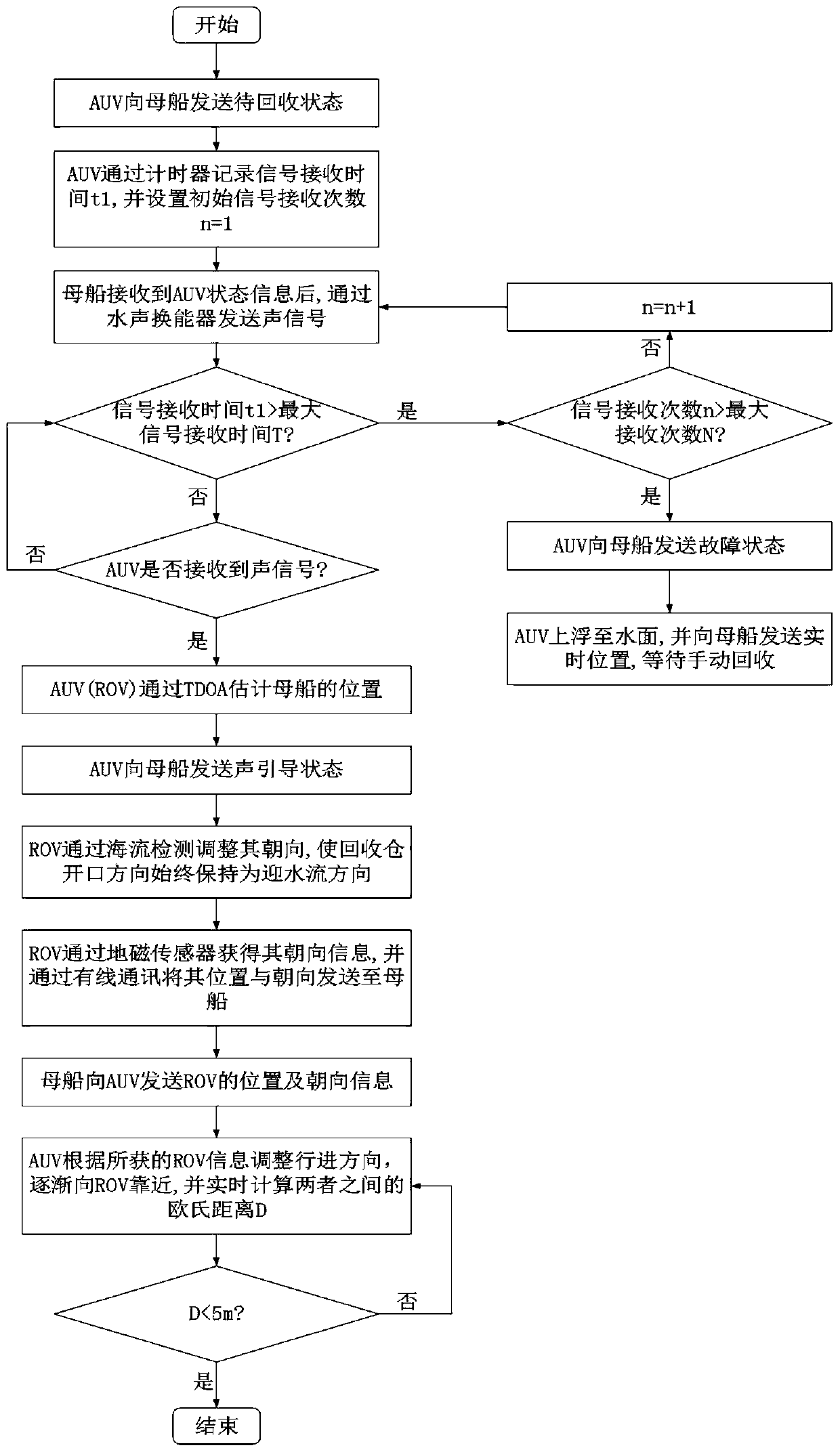
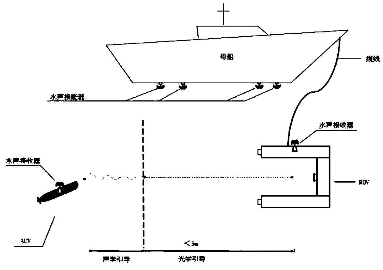
[0035] Embodiment: Acoustic guidance process: when the AUV enters the recovery stage, the underwater acoustic transducers arranged at four fixed positions at the bottom of the mother ship will send a signal every 5 seconds after receiving the recovery order, such as image 3 and Figure 4 As shown, the AUV and ROV receive signals through the underwater acoustic signal receiver. After receiving the signal, the arrival time of different signals is calculated by detection, and the difference between the arrival time of different signals (TDOA) is obtained, and further inverse Calculated as the measured distance difference between different underwater acoustic transducers, a set of nonlinear hyperbolic equations can be obtained, and the solution obtained by solving the corresponding equations is the relative position estimation of the mother ship relative to the AUV (or ROV). ROV Its relative position is transmitted back to the mother ship through underwater acoustic communication...


PUM


Abstract

The invention discloses an AUV capture guiding method based on acoustic and optical guiding. The method comprises the following steps that after a mother ship receives a to-be-recovered signal transmitted by an AUV, four underwater acoustic transducers are adopted to transmit an acoustic signal to the AUV; the AUV receives the acoustic signals and calculates the time difference of different signals arriving at the AUV, the relative position of the AUV and the mother ship is calculated according to the time difference, the AUV sends the position information and the acoustic guiding state of theAUV to the mother ship, and the mother ship sends the acoustic guiding state to an AUV recovery device ROV; the AUV detects a guiding lamp signal arranged on the AUV recovery device ROV; when the AUVrecovery device ROV rear wall guiding lamp signal is detected, the position of the AUV recovery device ROV is estimated by identifying the relative position of a guiding lamp on the rear wall in theAUV recovery device ROV relative to a coordinate system formed by guiding lamps on the front side of the AUV recovery device ROV.

Description

technical field [0001] The invention relates to the field of underwater robot control, in particular to an AUV capture and guidance method based on acoustic and optical guidance. Background technique [0002] AUV capture and guidance is the key issue in AUV recovery. At present, AUV recovery guidance mainly adopts acoustic guidance or optical guidance, but due to factors such as noise interference, the accuracy of underwater acoustic positioning is greatly affected, and the recovery cabin signal light Guided into the cabin, in the process of entering the cabin, it can only enter the cabin through inertia, which is prone to collisions and brings unnecessary damage to the AUV. There are two main types of existing underwater AUV recovery technologies. The first is the fishing method, which uses a net-like structure to catch the AUV directly ashore. This method can easily cause damage to the AUV; the second method uses the box body Or the recovery device is fixed on the seabed....

Claims


Application Information

Patent Timeline
Patent Type & Authority Applications(China)
IPC IPC(8): B63C11/52B63G8/00
CPCB63C11/52B63G8/001B63G2008/002
Inventor 付先平毕胜林鹏袁国良王辉兵张爱东张军
Owner DALIAN MARITIME UNIVERSITY
Why Eureka
Try Eureka