Distributed natural gas hydrogen production reactor

A hydrogen production reactor and natural gas technology, applied in hydrogen, chemical instruments and methods, inorganic chemistry, etc., can solve the problems of restarting the time interval, reducing the reaction coil temperature, reducing the service life of the device, etc., to achieve energy utilization Maximization, improved reaction efficiency, and less heat loss

Inactive Publication Date: 2012-07-25
HEFEI UNIV OF TECH
View PDF2 Cites 0 Cited by
  • Summary
  • Abstract
  • Description
  • Claims
  • Application Information

AI Technical Summary

Problems solved by technology

On the one hand, carbon monoxide and hydrogen are produced by the reaction of carbon deposits and steam, which is not pure hydrogen. If the purpose is to obtain pure hydrogen, the device needs to switch working conditions and cannot continue to operate; on the other hand, the introduction of steam reduces the capacity of the reaction coil. The temperature makes it impossible to continue the hydrogen production reaction by cracking natural gas, and it takes a time interval to restart; at the same time, when the incoming water vapor reacts with high-temperature carbon deposits, it will also cause denudation reactions to occur on the inner surface of the reaction coil, which reduces the operating efficiency of the device. service life

Method used


Image

  • Distributed natural gas hydrogen production reactor
  • Distributed natural gas hydrogen production reactor
  • Distributed natural gas hydrogen production reactor

Examples


Embodiment 1

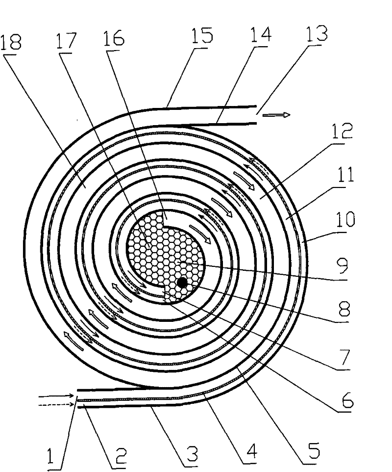
[0024] figure 1 A structural schematic diagram of this embodiment is given when the multiple counterflow heat exchanger 18 has a spiral ring shape, the number of turns of the intake passage and the exhaust passage 12 are 3, and the central reaction zone 17 is not divided.

[0025] The distributed natural gas hydrogen production reactor includes: an air inlet channel outer wall thin plate 3 and an air inlet channel inner wall thin plate 5, and an exhaust channel outer wall thin plate 15 and an exhaust channel inner wall thin plate 14 to form a bidirectional countercurrent annular inlet The channel and the exhaust channel 12, the porous medium 9 placed in the central reaction zone 17 in the multiple counterflow heat exchangers 18, and the ignition rod 8 placed in the porous medium 9.

[0026] In specific implementation, the number of turns of the annular intake passage and the annular exhaust passage 12 may be 3-20, and the shape may be a spiral ring shape or a spiral square ring shap...

Embodiment 2

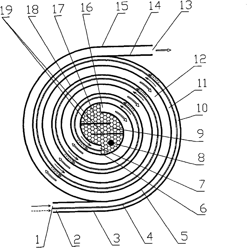
[0033] figure 2 The structure diagram of the embodiment in the case where the multi-strand counterflow heat exchanger 18 has a spiral ring shape, the number of turns of the intake passage and the exhaust passage 12 are three, and the central reaction zone 17 is arranged with two partitions 19 .

[0034] In this embodiment, two partitions 19 added to the central reaction zone 17 separate the central reaction zone 17 into a zigzag-shaped baffle channel. The rest of the structural features are the same as the first embodiment, and the operation method is also the same as the first embodiment.

Embodiment 3

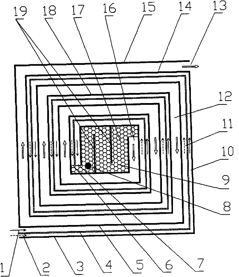
[0036] image 3 The embodiment structure in the case where the multiple counterflow heat exchanger 18 is a spiral square ring, the number of turns of the intake passage and the exhaust passage 12 are three, and the central reaction zone 17 is arranged with two partitions 19 Schematic.

[0037] The other structural forms in this embodiment are the same as those in the second embodiment, and the operating method is the same as in the first embodiment.


PUM


Abstract

The invention discloses a distributed natural gas hydrogen production reactor which comprises an annular gas inlet passage and an annular gas discharge passage which are refluent in two directions and formed by a gas inlet passage outer wall sheet and a gas inlet passage inner wall sheet as well as a gas discharge passage outer wall sheet and a gas discharge passage inner wall sheet. The distributed natural gas hydrogen production reactor is characterized in that an annular-stripe shaped gas inlet passage separation sheet is inserted in the gas inlet passage to divide the gas inlet passage into a first gas inlet passage and a second gas inlet passage. By the invention, fuel gas and oxidizing gas which are used in reaction can enter the center of the reactor in a non-premixed state, thereby avoiding flame drafting caused by premixing before the fuel gas and the oxidizing gas enter a porous medium and preventing the explosion hazard because of premixing. The distributed natural gas hydrogen production reactor can be widely applied to combustion reaction devices of low-concentration flammable gases, including oil layer gases in production of coal mine ventilation gas, natural gas, methane and petroleum, or flammable waste gas discharged in chemical production.

Description

Technical field [0001] The invention belongs to hydrogen production equipment, and particularly relates to a distributed natural gas hydrogen production reactor. Background technique [0002] Hydrogen energy, as a clean, efficient, safe, and sustainable energy source, is regarded as the clean energy with the most development potential in this century. It is also regarded as an effective alternative to secondary energy to solve the greenhouse effect and improve energy utilization. Hydrogen has a wide range of sources. Fossil fuels, plants, and organic waste all contain a large amount of hydrogen, but there is very little pure hydrogen that can be directly used in nature and can only be produced from other energy sources through specific methods. At present, 90% of hydrogen in the world is produced through natural gas steam reforming reaction or partial oxidation. [0003] Traditional large-scale hydrogen production from natural gas has been relatively slow due to the huge investmen...

Claims


Application Information

Patent Timeline
Patent Type & Authority Patents(China)
IPC IPC(8): C01B3/34C01B3/38
Inventor 唐志国程建萍马培勇
Owner HEFEI UNIV OF TECH
Why Eureka
Try Eureka