
Integrated high-pressure anti-blocking sucking, flushing and digging dredging equipment

A high-pressure, anti-blocking technology, applied in the direction of earth mover/shovel, mechanically driven excavator/dredger, construction, etc., can solve the problem of restricting the progress and development of dredging engineering technology, unable to meet actual needs, and low dredging efficiency and other problems, to achieve the effect of reducing the dredging intensity, simple and compact structure, and enhancing the dredging function

Inactive Publication Date: 2020-08-25
周鲲鹏
View PDF13 Cites 1 Cited by
  • Summary
  • Abstract
  • Description
  • Claims
  • Application Information

AI Technical Summary

Problems solved by technology

[0012] The dredging of small and medium-sized rivers is still dominated by manual operation, and the dredging efficiency is low and the effect is not good. The disclosed construction machinery technology is far from meeting the actual needs. Due to the limitation of construction technology and equipment, it is necessary to use different auxiliary machinery for separate construction, which also restricts the progress and development of dredging engineering technology.

Method used


Image

  • Integrated high-pressure anti-blocking sucking, flushing and digging dredging equipment
  • Integrated high-pressure anti-blocking sucking, flushing and digging dredging equipment
  • Integrated high-pressure anti-blocking sucking, flushing and digging dredging equipment

Examples


Embodiment

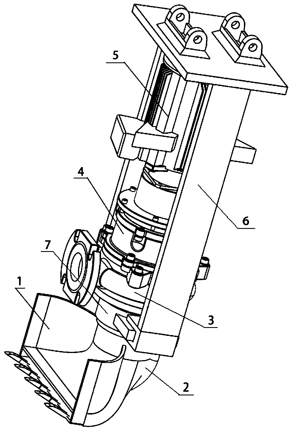
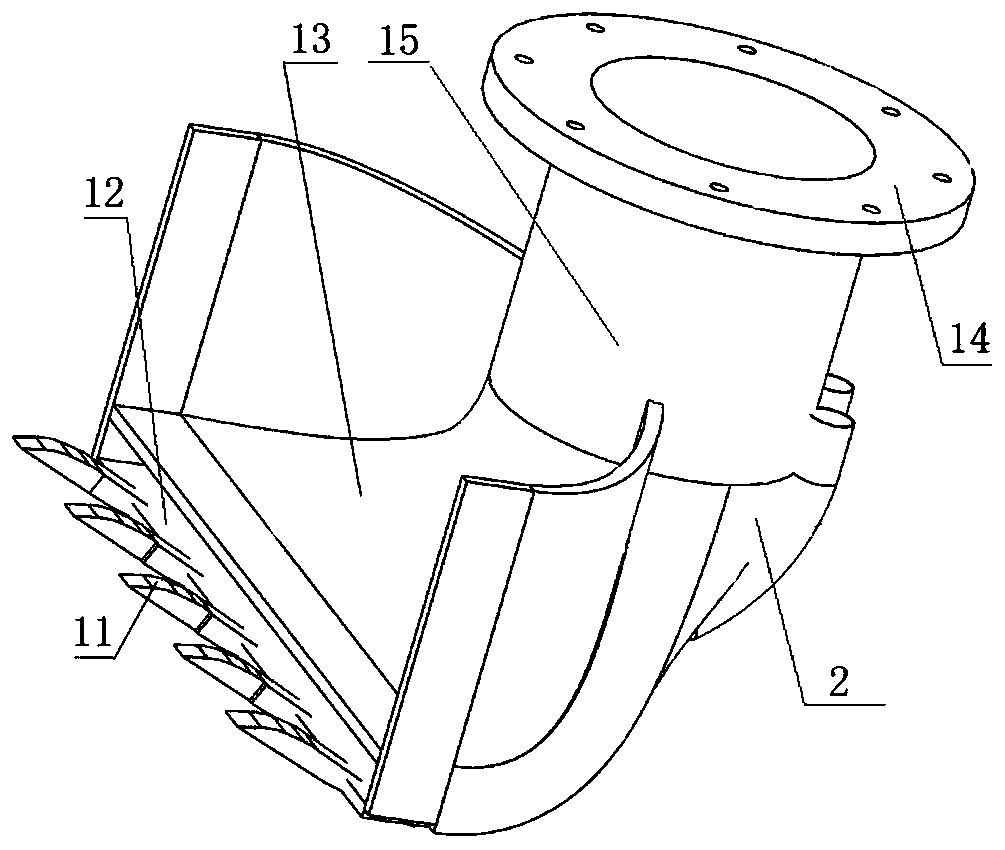
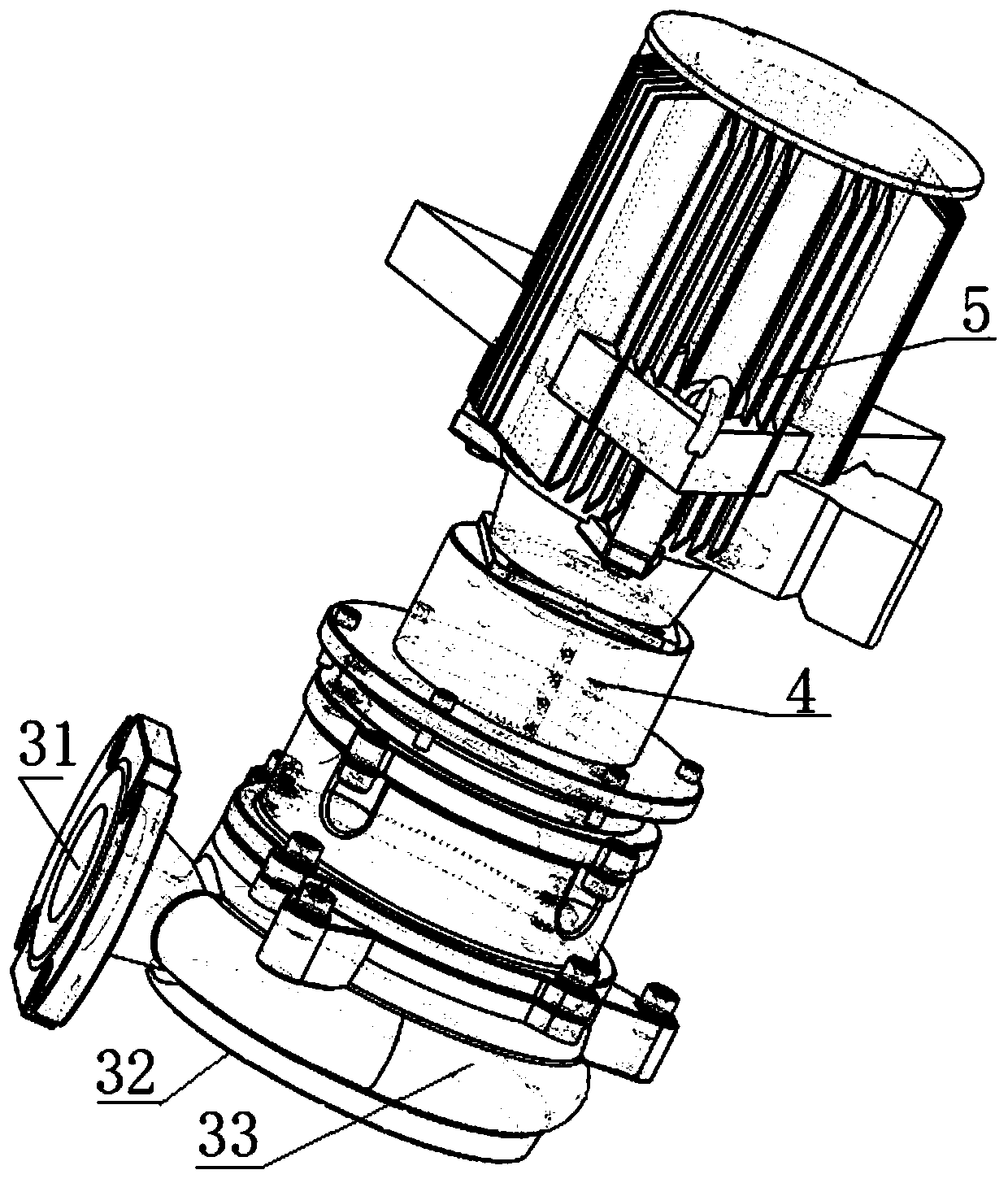
[0040] Example: as attached figure 1 , 2 , 3, 4, and 5, the top of the manipulator 1 is fixedly connected to the cutting pump 3 through the flange 14; the bottom of the manipulator 1 and the interior of the rear wall are cavity streamlined flow channels and communicate with the upper cutting pump 3, which can effectively reduce hydraulic loss The anti-clogging injection device 2 is welded on the back of the manipulator 1, and the bottom of the anti-silting injection device 2 communicates with the interior of the manipulator 1; the upper end of the cutting pump 3 is connected with the hydraulic motor 5 through the coupling 4, and the cutting pump 3, the coupling 4 and the The main equipment of the hydraulic motor 5 is fixedly connected with the mechanical connecting frame 6 by bolts through a hoop 7 .

[0041] In the foregoing, the manipulator 1 includes rake teeth 11 , a flat mud inlet 12 , a bucket 13 , a flange 14 and a connecting pipe 15 . The manipulator 1 uses a shovel-...


PUM


Abstract

The invention relates to integrated high-pressure anti-blocking sucking, flushing and digging dredging equipment. The top of a mechanical arm (1) and a cutting pump (3) are fixedly connected through aflange (14). The interiors of the bottom and the rear wall of the mechanical arm (1) are arranged to be flow channels of a cavity streamline structure and communicate with the cutting pump (3) on theupper portion. A anti-silting jetting device (2) is welded to the back of the mechanical arm (1), and the bottom of the anti-silting jetting device (2) communicates with the interior of the mechanical arm (1). The upper end of the cutting pump (3) is connected with a hydraulic motor (5) through a coupling (4), and body equipment of the cutting pump (3), the coupling (4) and the hydraulic motor (5) is in fixed bolt connection with a mechanical connecting frame (6) through a hoop (7). The integrated high-pressure anti-blocking sucking, flushing and digging dredging equipment integrates the functions of flushing, digging and sucking; and the problem of blocking of a silt suction port can be effectively solved through cooperative carrying work with a digging machine in combination with the spiral structure and the sharp knife edge structure of the cutting pump. The dredging function is remarkably enhanced, the internal silt conveying cavity streamline structure is adopted, hard waste is isolated based on the gravity principle, manual dredging intensity is greatly replaced or relieved, and the integrated high-pressure anti-blocking sucking, flushing and digging dredging equipment is suitable for mechanized dredging o f different working conditions of medium and small river channels.

Description

technical field [0001] The invention relates to underwater dredging mechanical equipment, which belongs to the technical field of excavation or dredging of IPC classification E02F5 / 00 water conservancy dredging projects, and in particular relates to integrated high-pressure anti-blocking suction scour dredging equipment. Background technique [0002] The dredging project of small and medium-sized rivers in cities and rural rivers generally intercepts both sides of the river, then pumps out the water, and excavates manually or with an excavator. Smell, great impact on the surrounding environment. [0003] At present, it is more and more difficult to rely on manual dredging, and it is urgent to realize the mechanization of dredging work. Large-scale dredging equipment and dredging vessels are basically built for large-scale dredging projects in ports, waterways or large rivers, and cannot enter small and medium-sized rivers for construction; if the hinged suction method is us...

Claims


Application Information

Patent Timeline
Patent Type & Authority Applications(China)
IPC IPC(8): E02F3/88E02F3/90E02F3/92E02F5/28
CPCE02F3/88E02F3/90E02F3/92E02F3/9212E02F3/9225E02F5/28E02F5/282E02F5/285E02F5/287
Inventor 周鲲鹏
Owner 周鲲鹏
Learn More