
Moving bottom plug

A sleeve and breathing tube technology, applied in the field of swimming bottom plugging, can solve the problems of piston effect in the unsealing process of the lower packer, increased unsealing load, difficulty in unsealing, etc., so as to eliminate the piston effect and reduce the resistance , Ease of sealing and unsealing

Pending Publication Date: 2020-08-25
CHINA PETROLEUM & CHEM CORP +1
View PDF0 Cites 2 Cited by
  • Summary
  • Abstract
  • Description
  • Claims
  • Application Information

AI Technical Summary

Problems solved by technology

[0003] The purpose of the present invention is to provide a floating bottom plug to solve the technical problem that the piston effect will be formed during the unsealing process of the lower packer in the prior art, resulting in increased unsealing load and difficulty in unsealing

Method used


Image

  • Moving bottom plug
  • Moving bottom plug
  • Moving bottom plug

Examples


specific Embodiment 1

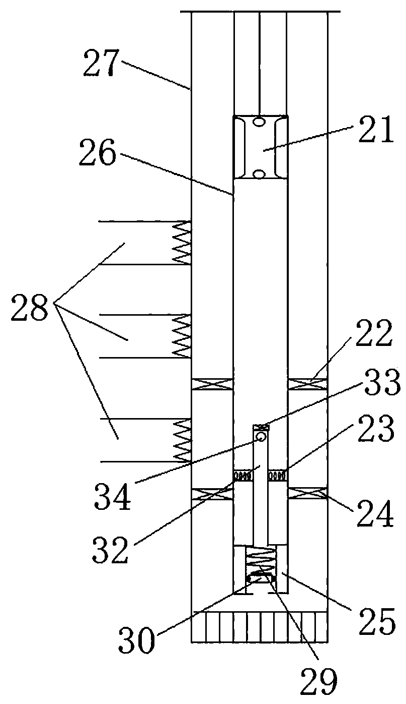
[0040] The swimming bottom plugging in this embodiment is applied to the structure of the pump-seal integrated water pipe string, such as figure 2 As shown, the pump-seal integrated water pipe string includes an oil pipe 26, and the oil pipe 26 includes a large number of pipe string sections connected in series. The oil well pump 21 is arranged inside the oil pipe 26, and a sucker rod is connected to the upper end of the oil well pump 21, and the oil sucker rod drives pumping. Oil pump 21 carries out oil pumping operation. The oil pipe 26 is connected with an upper packer 22 and a lower packer 24 below the oil pump 21, and the upper packer 22 and the lower packer 24 are arranged at intervals in the vertical direction to separate each oil layer 28 .

[0041] In this embodiment, the upper packer 22 is a Y111 packer, and the lower packer 24 is a Y211 packer, wherein both the Y111 packer and the Y211 packer are mature products in the prior art.

[0042] Among them, the oil pipe...

specific Embodiment 2

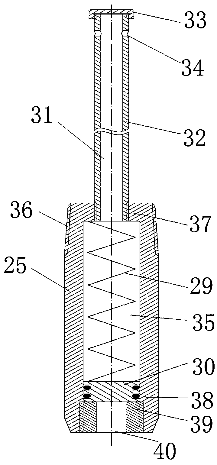
[0060] The difference from the specific embodiment 1 is that in embodiment 1, a wire plug 33 is provided at the opening of the upper end of the breathing tube 32, and a breathing hole 34 is provided on the breathing tube 32, and the breathing hole 34 is used to communicate with the deposition ring cavity and the breathing tube 32. The inner cavity of the breathing tube 34 is set close to the plug 33. In this embodiment, the opening at the upper end of the breathing tube is not blocked, and the upper end of the breathing tube is bent towards the sleeve, that is, the opening of the breathing tube is facing the sleeve. At this time The sediment in the oil pipe will not enter into the breathing pipe, so it can prevent impurities from depositing on the piston in the sleeve and blocking the piston. Wherein, the opening of the breathing tube in this embodiment forms a breathing port, and the breathing port provides a passage for liquid in and out for the up and down movement of the pi...

specific Embodiment 3

[0062] The difference from Embodiment 1 is that in Embodiment 1, the plugging structure is a wire plug 33, and the wire plug 33 is used to block the upper opening of the breathing tube 32. In this embodiment, the plugging structure is welded on the upper end of the breathing tube. Sealing plate at the opening. In other embodiments, the blocking structure is a cover integrally formed with the breathing tube; or the blocking structure is a sealing plate fixedly connected to the upper opening of the breathing tube by bolts.


PUM


Abstract

The invention relates to a moving bottom plug. The moving bottom plug comprises a sleeve, a piston and an elastic piece, the sleeve extends in the vertical direction, an oil pipe connecting structureis arranged at the upper end of the sleeve and used for being connected with a corresponding pipe column section of an oil pipe, a sleeve pipe communicating port is formed in the lower end of the sleeve and used for communicating with the portion, below a lower packer, of a cavity of a sleeve pipe, the piston is assembled in the sleeve in a sliding and sealing mode in the vertical direction and used for adjusting the volume of the portion, below the lower packer, of the cavity of the sleeve pipe, an upper limit position and a lower limit position which are located in the sleeve are provided inthe reciprocating sliding stroke of the piston, the elastic piece is arranged in the sleeve, and the elastic piece applies elastic force towards the sleeve pipe communicating port to the piston in the well entering process of pipe column sections so as to prevent the piston from moving upwards to the upper limit position. When a pipe column is lowered for setting or lifted for unsetting, the up-down pressure of the piston is balanced, the piston effect is eliminated, and setting and unsertting of the pipe column are facilitated.

Description

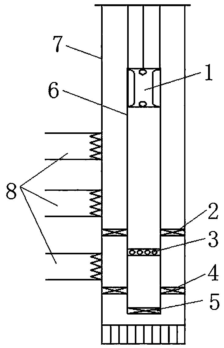
technical field [0001] The invention relates to a floating bottom plug. Background technique [0002] In the middle and late stage of oilfield development, especially in the late stage of oilfield development by water flooding, with the change of formation water content, the layers are divided more and more finely, the contradiction between layers becomes more and more prominent, and high and low aquifers coexist. In order to understand oil layers, stabilize Oil control water, often need to find water plugging work. At present, the commonly used pipe string in the operation of finding plugging water is the pipe string with integrated pump seal and double seal, such as figure 1 As shown, the tubing string is connected with the upper packer 2, the screen 3, the lower packer 4 and the plug 5 in sequence on the tubing 6 under the well pump 1. The tail is connected with a plug 5, and after the two packers are set, a dead space will be formed between the casing 7 below the lower...

Claims


Application Information

Patent Timeline
Patent Type & Authority Applications(China)
IPC IPC(8): E21B23/00E21B17/00
CPCE21B23/00E21B17/00
Inventor 秦世群黄逊王登辉高涛郭亮孙爱军吴娜娜张峰代吉建
Owner CHINA PETROLEUM & CHEM CORP
Learn More