Plastic pipeline applicable to municipal sewer, provided with self-cleaning structure and used for pollution discharging and water drainage
A self-cleaning, sewer technology, applied in cleaning methods and appliances, pipeline protection, cleaning hollow objects, etc., can solve the problems of fast flow rate, reduce the service life of pipelines, impact, etc., to avoid bursting, prolong service life, and ensure circulation Effect
- Summary
- Abstract
- Description
- Claims
- Application Information
AI Technical Summary
Problems solved by technology
Method used
Image
Examples
Embodiment 1
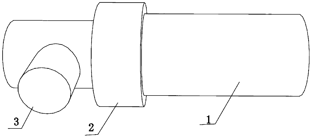
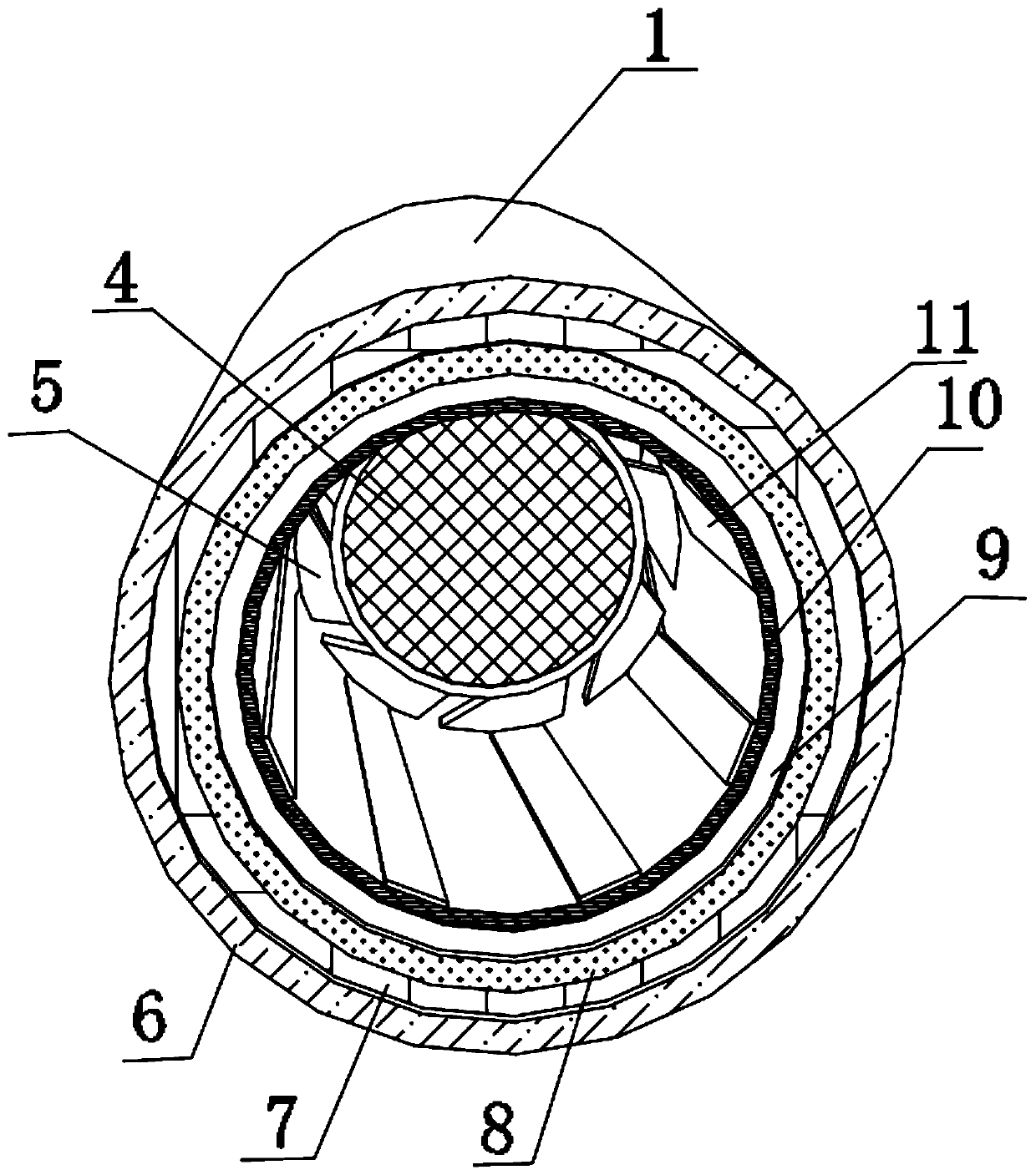
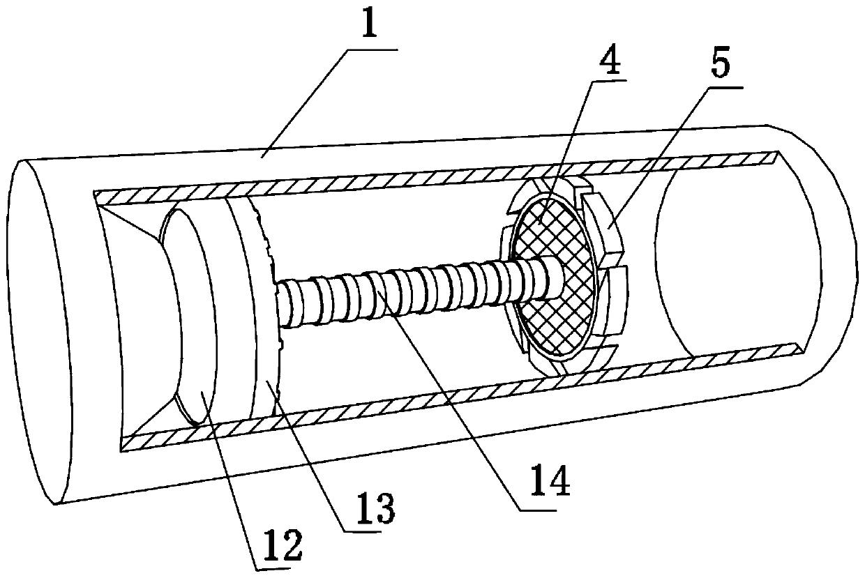
[0028] A plastic pipe for sewage and drainage with a self-cleaning structure for municipal sewers, such as image 3 and Figure 4 As shown, it includes a pipe body 1, one end of the pipe body 1 is fixed with a slow flow plate 15 by bolts, the slow flow plate 15 is in a tapered structure, and one end of the slow flow plate 15 is provided with a drain port 16; the pipe body 1 The inner wall close to the slow flow plate 15 is fixed with a flow equalizer 13 by bolts, and the outer wall of one side of the flow equalizer 13 is provided with a water inlet 12. Enter the equalizer plate 13 to perform slow flow and equalization, reduce the flow velocity of the water flow, reduce the impact of the water flow on the pipeline, increase the service life of the pipeline, and reduce the output of maintenance or replacement costs.
[0029] In order to further reduce the impact of water flow on the pipeline; Figure 4 As shown, the outer wall of one side of the flow equalizer 13 is fixed with...
Embodiment 2
[0035] A plastic pipe for sewage and drainage with a self-cleaning structure for municipal sewers, such as Figure 3-5 As shown, in order to further ensure that the inside of the pipeline will not retain dirt; this embodiment makes the following improvements on the basis of embodiment 1: one side of the outer wall of the partition plate 17 is welded with an elastic sleeve 14, and the other of the elastic sleeve 14 One end is welded with an inlet and outlet 4, the inlet and outlet 4 are in a mesh structure, the outer wall of the inlet and outlet 4 is welded with a rubber ring 19, the inner wall of the rubber ring 19 is placed with a spring 20, and the two ends of the spring 20 are respectively connected to the inlet and outlet 4 and the outlet through bolts. The partition plate 17 is connected with each other. When the water flow is large, the spring 20 is elastically deformed, and the flow velocity of the water is used to push the inlet and outlet 4 to move forward inside the p...
PUM
 Abstract
Description
Claims
Application Information
 - R&D
- Intellectual Property
- Life Sciences
- Materials
- Tech Scout
- Unparalleled Data Quality
- Higher Quality Content
- 60% Fewer Hallucinations
Browse by: Latest US Patents, China's latest patents, Technical Efficacy Thesaurus, Application Domain, Technology Topic, Popular Technical Reports.
© 2025 PatSnap. All rights reserved.Legal|Privacy policy|Modern Slavery Act Transparency Statement|Sitemap|About US| Contact US: help@patsnap.com


