
Impinging stream low-nitrogen combustion reaction device and reaction method thereof

A technology of impinging flow reaction and low-nitrogen combustion, applied in combustion methods, burners, combustion chambers, etc., to achieve uniform heat release and high heat utilization efficiency

Pending Publication Date: 2020-08-25
江苏河海新能源技术发展有限公司
View PDF1 Cites 2 Cited by
  • Summary
  • Abstract
  • Description
  • Claims
  • Application Information

AI Technical Summary

Problems solved by technology

[0007] In the combustion reaction, it is usually necessary to introduce cost-free and easily obtained air as a combustion aid. The air contains a large amount of nitrogen. Usually, nitrogen does not react with oxygen. When the oxygen content is insufficient, the nitrogen temperature is around 1350 ° C , will react with oxygen to generate toxic thermal NOx, while the temperature required in the traditional burner usually reaches a high temperature above 1400 or even 1500°C, and it is very easy to generate toxic NOx

Method used


Image

  • Impinging stream low-nitrogen combustion reaction device and reaction method thereof
  • Impinging stream low-nitrogen combustion reaction device and reaction method thereof
  • Impinging stream low-nitrogen combustion reaction device and reaction method thereof

Examples


Embodiment Construction

[0036] The following is based on the ideal embodiment of the present invention as an inspiration. Through the following description, relevant workers can make various changes and modifications within the scope of not departing from the technical idea of ​​the present invention. The technical scope of the present invention is not limited to the content in the specification, but must be determined according to the scope of the claims.

[0037] With reference to the following drawings, the present invention is further described:

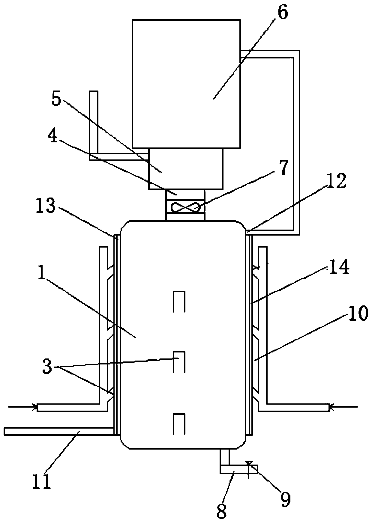
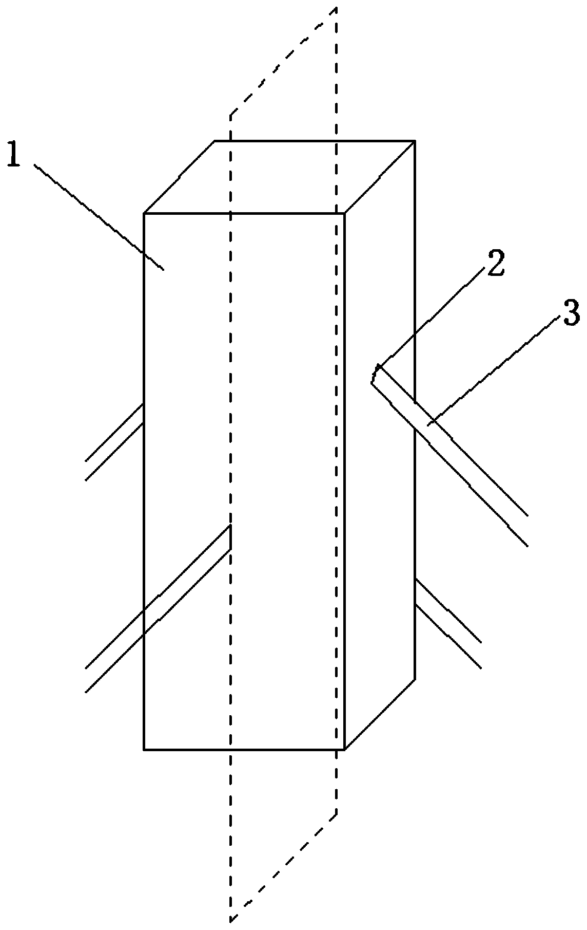
[0038] An impinging flow low-nitrogen combustion reaction device, comprising the following components:

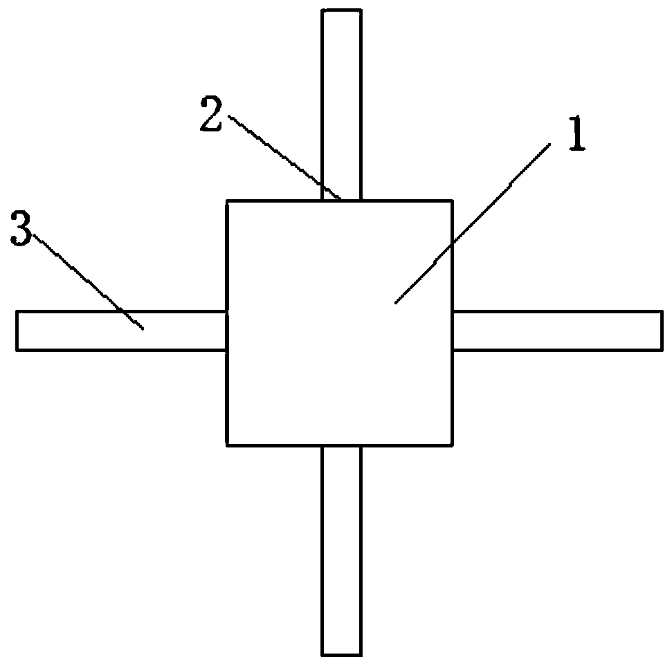
[0039] The impingement flow reaction chamber 1 of a cylinder or a cuboid, the side of the impingement flow reaction chamber 1 is evenly opened with several layers of installation through holes 2 from bottom to top, the installation through holes 2 of the same layer are of the same height and coaxial, and the installation through holes 2 of adjacent l...


PUM


Abstract

The invention relates to the technical field of chemical industry, and in particular to an impinging stream low-nitrogen combustion reaction device. The impinging stream low-nitrogen combustion reaction device comprises the following parts of a cylindrical or rectangular impinging stream reaction chamber, wherein the side of the impinging stream reaction chamber is uniformly opened with several layers of installation through holes from bottom to top; acceleration tubes installed in the installation through holes; an air flow channel installed on the top of the impinging stream reaction chamberand communicated with the impinging stream reaction chamber; a burner communicated with the other end of the air flow channel; and a boiler installed on the top of the burner and providing heat by the burner. The invention also discloses an impinging stream low-nitrogen combustion reaction method, which specifically comprises the following steps of introducing high-speed air and high-speed gas into the acceleration tubes in the same layer for collision to obtain a rising ion current; driving the turbulence fan to rotate by the rising ion current when passing through a turbulence fan so as toevenly mix the ions in the ion flow, and making the ion flow continue to rise into the burner; heating the burner to 1000 to 1100 DEG C to cause the ion flow to burn and release heat; and exhausting excess nitrogen and water.

Description

technical field [0001] The invention relates to the technical field of chemical industry, in particular to an impinging flow low-nitrogen combustion reaction device and a reaction method thereof. Background technique [0002] The impinging flow reactor achieves a very high relative velocity between the phases at the moment of impact through the impact of two gas phase flows at high speed, thereby greatly enhancing the interphase transfer. [0003] The patent application number CN200420017226.4 discloses an impinging flow gas-liquid reactor, which is described as follows in its abstract: [0004] The utility model relates to an impinging flow gas-liquid reactor, which belongs to chemical reaction technical equipment. A horizontal coaxial two-flow impingement flow is used. [0005] The accelerating tube of this kind of impinging flow reactor is horizontally coaxial, and can only be impacted on the opposite side of the accelerating tube nozzle. After the impact, additional en...

Claims


Application Information

Patent Timeline
Patent Type & Authority Applications(China)
IPC IPC(8): F23R3/28F23D14/02F23D14/64F23D14/70F24H1/00F24H9/18B01J19/24
CPCF23R3/286F23D14/02F23D14/64F23D14/70B01J19/2405F24H1/0027F24H9/1809F24H9/1836
Inventor 杨家华万文雷秦华云史亦丰席跃跃
Owner 江苏河海新能源技术发展有限公司
Learn More