Cleaning tank structure on semiconductor silicon wafer cleaning machine
A silicon wafer cleaning and cleaning tank technology, which is used in semiconductor/solid-state device manufacturing, electrical components, circuits, etc., can solve the problems of high consumption of pure water and increased consumption of pure water, and achieve the effect of saving water and energy and reducing consumption.
- Summary
- Abstract
- Description
- Claims
- Application Information
AI Technical Summary
Problems solved by technology
Method used
Image

Examples
Embodiment
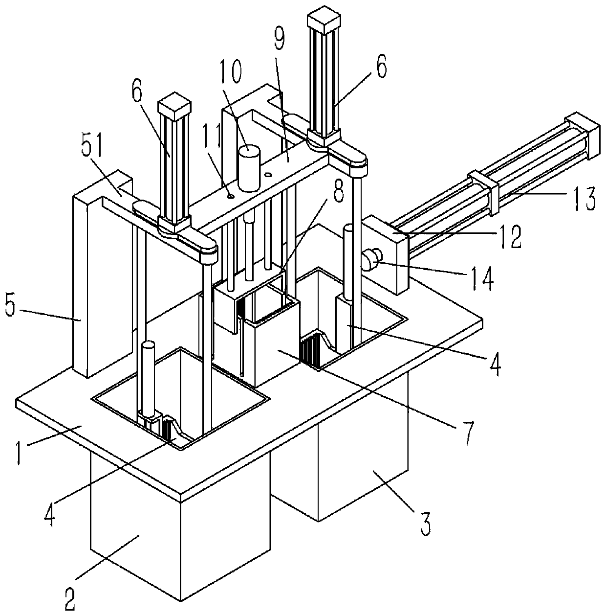
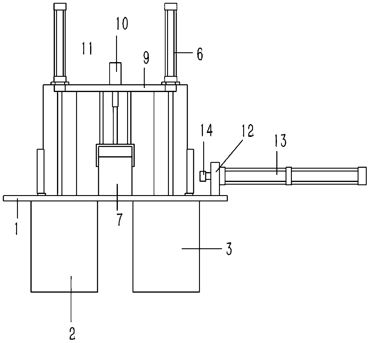
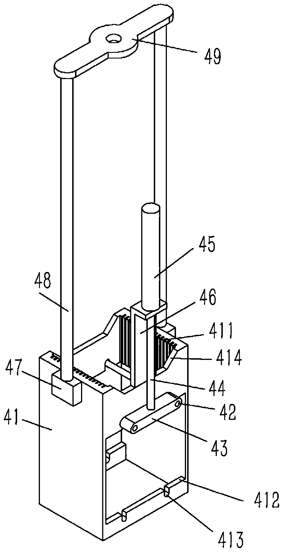
[0024] Example: see Figures 1 to 6 As shown, a cleaning tank structure on a semiconductor silicon wafer cleaning machine includes a cleaning table 1 on the cleaning machine. A liquid medicine tank 2 and a pure water tank 3 are plugged and fixed on the cleaning table 1. Inserted with a silicon chip carrying bracket 4, the silicon chip supporting bracket 4 includes a rectangular frame 41, the inner wall of the front and rear sides of the upper part of the frame 41 is formed with a number of relative slots 411, the front and rear of the lower part of the frame 41 The inner wall of the side is formed with a slot that is connected with the slot 411 and runs through the lower end surface of the frame body 41. The outer wall of the frame body 41 on both sides of the slot is formed with an inlet and outlet notch 412, and the upper and lower bottom surfaces of the inlet and outlet notch 412 There are several relative positioning grooves 413 formed, and several horizontal support rods ...
PUM
 Abstract
Description
Claims
Application Information
 - R&D
- Intellectual Property
- Life Sciences
- Materials
- Tech Scout
- Unparalleled Data Quality
- Higher Quality Content
- 60% Fewer Hallucinations
Browse by: Latest US Patents, China's latest patents, Technical Efficacy Thesaurus, Application Domain, Technology Topic, Popular Technical Reports.
© 2025 PatSnap. All rights reserved.Legal|Privacy policy|Modern Slavery Act Transparency Statement|Sitemap|About US| Contact US: help@patsnap.com