Audio modulation circuit and electronic equipment

An audio modulation and circuit technology, applied in the direction of electrical components, gain control, amplification control, etc., can solve the problem of high power consumption of audio amplifiers

Pending Publication Date: 2020-08-25
上海艾为集成电路技术有限公司
View PDF3 Cites 4 Cited by
  • Summary
  • Abstract
  • Description
  • Claims
  • Application Information

AI Technical Summary

Problems solved by technology

[0005] In view of this, the application provides an audio modulation circuit and an el...

Method used


Image

  • Audio modulation circuit and electronic equipment
  • Audio modulation circuit and electronic equipment
  • Audio modulation circuit and electronic equipment

Examples


Embodiment Construction

[0044] The technical solutions in the embodiments of the present application will be clearly and completely described below in conjunction with the accompanying drawings. Apparently, the described embodiments are only some of the embodiments of the present application, not all of them. Based on the embodiments in this application, all other embodiments obtained by those skilled in the art without making creative efforts belong to the scope of protection of this application. In the case of no conflict, the following embodiments and technical features thereof can be combined with each other.

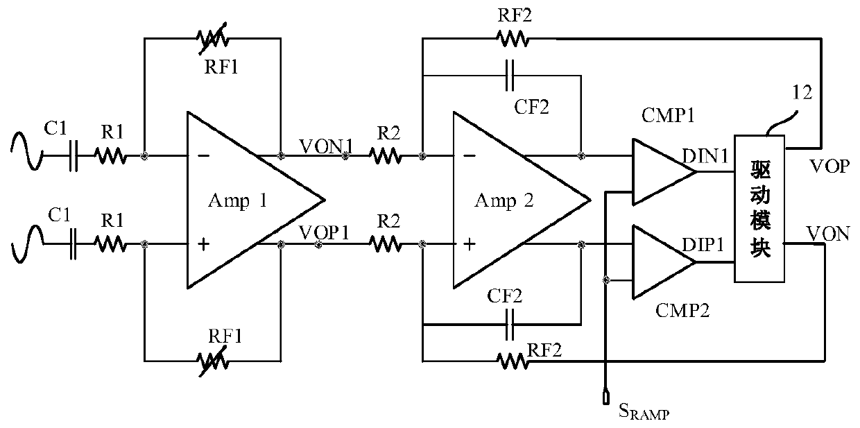
[0045] Please refer to Figure 1a , is a schematic structural diagram of an audio modulation circuit according to an embodiment of the present invention.

[0046] In this embodiment, the audio modulation circuit is used to process a pair of differential signals, and the pair of differential signals are respectively coupled to the input terminals of the amplifier Amp1 for full differential ...


PUM


Abstract

The invention discloses an audio modulation circuit and electronic equipment. The audio modulation circuit comprises a common-mode modulator, wherein the common-mode modulator is used for comparing apair of differential signals of which the level values are symmetrical about a common-mode reference voltage with a first reference voltage and a second reference voltage, and dynamically adjusting the common-mode reference voltage on the basis of a preset common-mode reference voltage VC according to a comparison result. The power consumption of the audio modulation circuit is reduced.

Description

technical field [0001] The present application relates to the technical field of signal modulation, in particular to an audio modulation circuit and an electronic device. Background technique [0002] A Class D audio amplifier is a commonly used high-efficiency amplifier for amplifying audio signals. In a system using a Class D amplifier, an analog input signal is converted into a series of pulse-modulated signals with different pulse widths to drive audio speakers. [0003] The existing class D audio amplifier usually has two output terminals, which are respectively connected to the positive and negative poles of the load, and an LC filter structure or a switch control circuit is usually connected between the output terminals and the positive and negative poles of the load. Whether it is static or dynamic working state, the output signal will cause a large power consumption in the LC filter structure or switch control circuit. [0004] As portable devices such as smart pho...

Claims


Application Information

Patent Timeline
IPC IPC(8): H03F3/217H03G3/30
CPCH03F3/217H03G3/3005
Inventor 薛蓉
Owner 上海艾为集成电路技术有限公司
Why Eureka
Try Eureka