
Sound producing device and method of manufacturing sound producing device

A technology for generating device and sound, which can be applied in the direction of sound-producing equipment, fluid using vibration, transducer of piezoelectric-electric polymer, etc., which can solve the problem of high material cost, brittle conductive adhesive, increased manufacturing cost and labor hours. and other problems, to achieve the effect of high strength, sufficient conductivity and low cost

Pending Publication Date: 2020-08-25
HOSIDEN CORP
View PDF1 Cites 0 Cited by
  • Summary
  • Abstract
  • Description
  • Claims
  • Application Information

AI Technical Summary

Problems solved by technology

[0003] Conductive adhesives have the disadvantages of being brittle and having high material costs compared to other adhesives
[0004] In the case of replacing the conductive adhesive with a thermosetting adhesive, the strength increases and the material cost decreases, but the piezoelectric element is insulated from the thin metal plate, and a complicated structure is required to apply a voltage to the piezoelectric element, so the manufacturing cost , working hours increase

Method used


Image

  • Sound producing device and method of manufacturing sound producing device
  • Sound producing device and method of manufacturing sound producing device
  • Sound producing device and method of manufacturing sound producing device

Examples


Embodiment 1

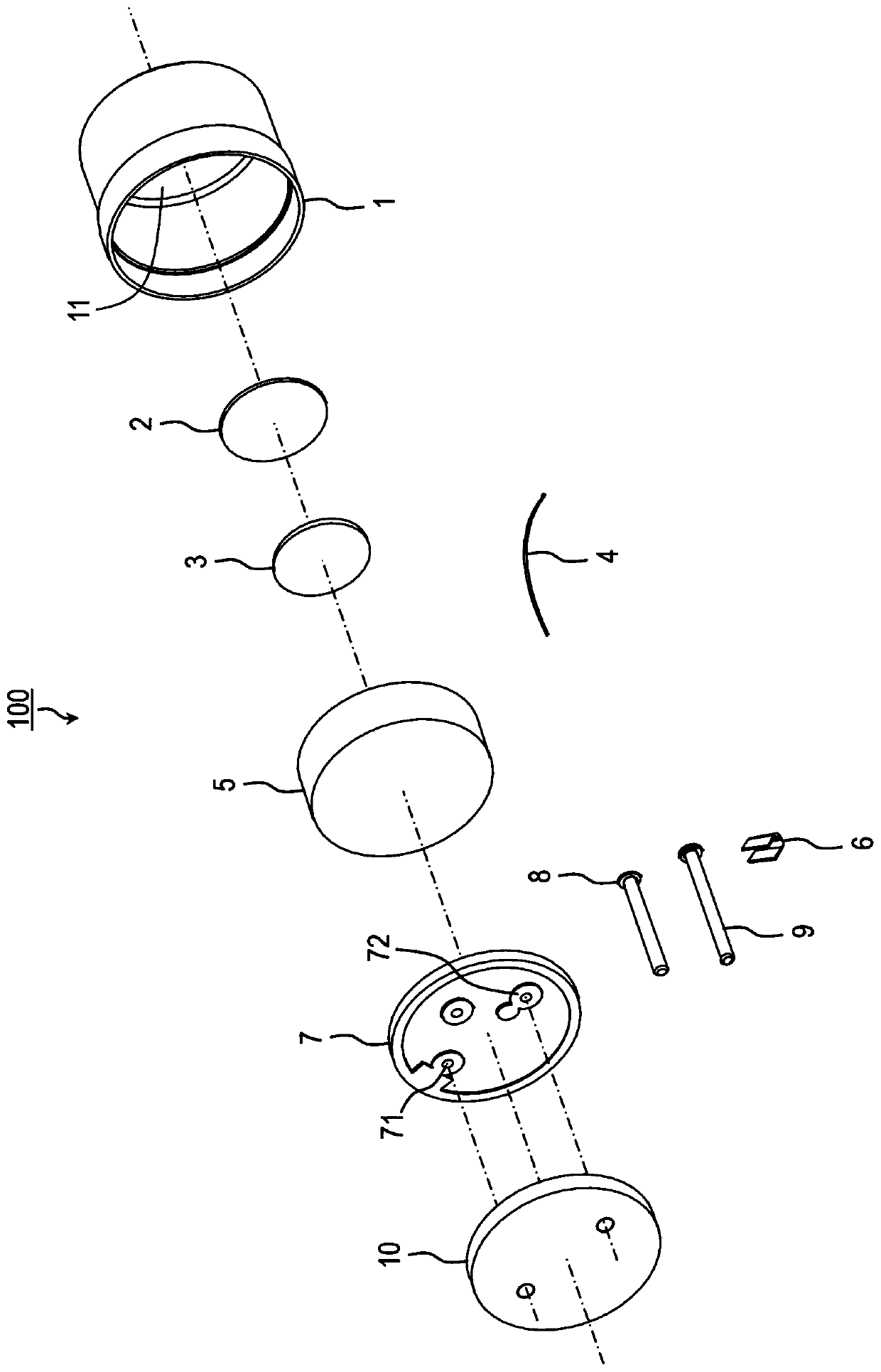
[0013] Below, refer to figure 1 The sound generator 100 of the first embodiment will be described. As shown in this figure, the sound generating device 100 is constituted to include: a cylindrical metal case 1 comprising a bottom surface and a cylindrical surface with an opening on the top; a thin disc-shaped adhesive layer 2; a thin disc-shaped The piezoelectric ceramic (piezoelectric element) 3 is bonded to the bottom surface (inner surface) of the metal case 1 through the adhesive layer 2; the cable 4 connects the piezoelectric ceramic (piezoelectric element) 3 and the substrate 7 Electrical connection; disk-shaped sponge 5, which is sandwiched between piezoelectric ceramics (piezoelectric element) 3 and substrate 7; copper foil 6, which fixes cable 4 to substrate 7; disk-shaped substrate 7; welding Negative-side pins 8 and positive-side pins 9 on the upper surface of the substrate 7 ; and a disk-shaped sealant 10 .

[0014]

[0015] In the cylindrical metal case 1, the...


PUM


Abstract

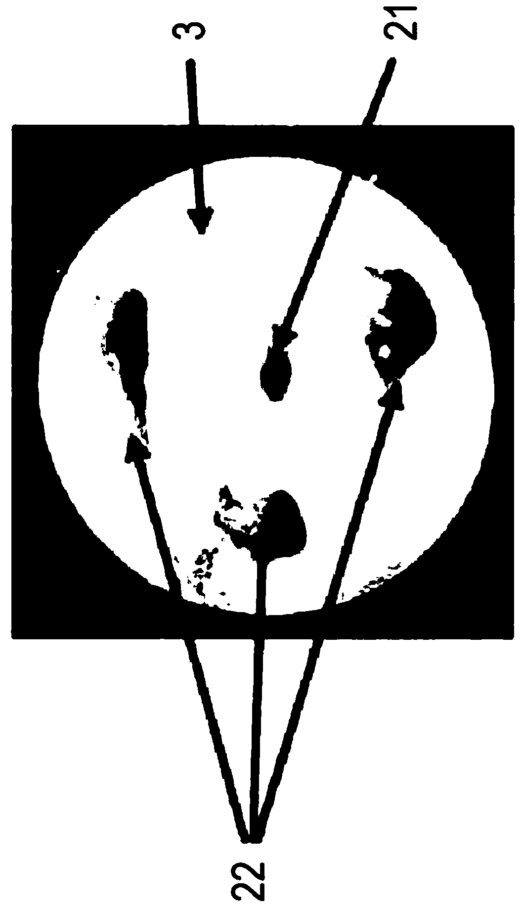
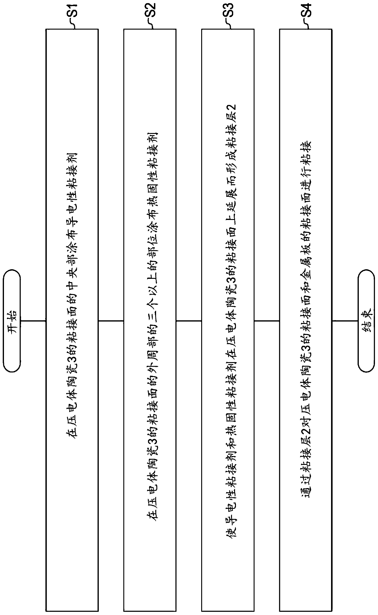
Provided is a sound producing device which is low in cost and high in strength, and in which an adhesive layer between a piezoelectric element and a metal plate has sufficient conductivity. The devicecomprises: a metal plate; a piezoelectric ceramic that includes a first adhesive surface that is a surface to be adhered to the metal plate; an alternating-current power supply for applying an alternating-current voltage to the piezoelectric ceramic; an adhesive layer formed by extending, on the first adhesive surface, a conductive adhesive applied to the central portion of the first adhesive surface and a thermosetting adhesive applied to three or more portions of the outer peripheral portion of the first adhesive surface; the bonding surface of the metal plate and the piezoelectric ceramicserves as a second bonding surface, and the first bonding surface and the second bonding surface are bonded through a bonding layer.

Description

technical field [0001] The present invention relates to sound generating devices and methods of manufacturing sound generating devices. Background technique [0002] As a prior art of a piezoelectric vibrating plate, there is, for example, Patent Document 1 (Patent Document 1: Japanese Patent Application Laid-Open No. 1-170299). In the piezoelectric vibration plate of Patent Document 1, in the piezoelectric vibration plate in which the piezoelectric element is bonded to the thin metal plate through the adhesive layer, the adhesive layer between the piezoelectric element and the thin metal plate is used to make the conductivity It is formed by mixing organic substances such as resin solutions into conductive adhesives. [0003] Conductive adhesives have the disadvantages of being brittle and having high material costs compared to other adhesives. [0004] In the case of replacing the conductive adhesive with a thermosetting adhesive, the strength increases and the material ...

Claims


Application Information

Patent Timeline
Patent Type & Authority Applications(China)
IPC IPC(8): H04R17/00H04R31/00H10N30/073H10N30/853
CPCH04R17/005H04R31/00G10K9/122H04R17/00H04R31/006B06B1/0662H10N30/073H10N30/853
Inventor 井上良花井祯藤原悟
Owner HOSIDEN CORP
Learn More