Grain dust removing equipment and use method thereof

A dust removal equipment and grain technology, which is applied in grain drying, lighting and heating equipment, chemical instruments and methods, etc., can solve the problems of increasing labor intensity of workers, time-consuming and laborious, and low dust removal efficiency

Active Publication Date: 2020-08-28
宁夏明翔粮油有限公司
View PDF5 Cites 7 Cited by
  • Summary
  • Abstract
  • Description
  • Claims
  • Application Information

AI Technical Summary

Problems solved by technology

During the crop harvest season, the grains are collected mechanically or manually by the people, but it is inevitable that weeds or the hulls of the grains will be mixed in the collection of the grains, and the grains themselves will also be contaminated with dust, which brings a lot of trouble to people.
[0003] However, although the grain dedusting devices on the market can remove the dust in the grain, they still have the following defects: 1. The dust remov

Method used


Image

  • Grain dust removing equipment and use method thereof
  • Grain dust removing equipment and use method thereof
  • Grain dust removing equipment and use method thereof

Examples


Embodiment 1

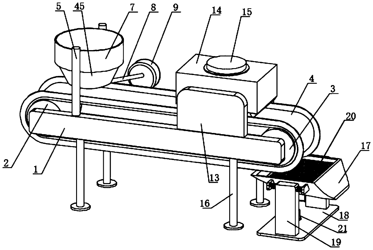
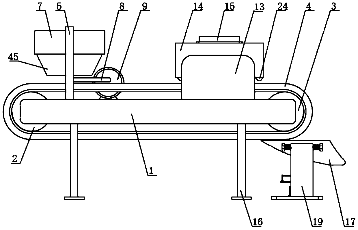
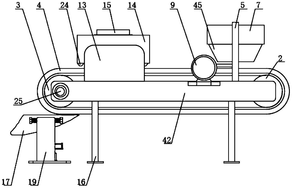
[0051] Example one: such as Figure 1-18 As shown, a grain dust removal equipment includes a first side plate 1 and a second side plate 42. The first side plate 1 is located on one side of the second side plate 42 and the first side plate 1 and the second side plate 42 are close to each other The first roller 2 and the second roller 3 are rotatably connected to one side of the second side plate 42. A driving motor 25 is fixedly installed on one side of the second side plate 42. The roller 3 is connected by a coupling. The outer wall of the first roller 2 and the outer wall of the second roller 3 are connected with the same sidewall conveyor 4, the top side of the first side plate 1 and the second side plate The top side of the 42 is fixedly installed with a vertical rod 5, and the top of the two vertical rods 5 close to each other is welded with the same discharge box 7. The discharge box 7 is located directly above the sidewall conveyor 4, and the discharge box A circular hol...

Embodiment 2

[0067] Embodiment two: such as Figure 19 with 20 As shown, there is a grain dust removal equipment. The difference between this embodiment and the first embodiment is that: the top of the first side plate 1 and the top of the second side plate 42 are fixedly installed with a plurality of mounting rods 11 arranged at equal intervals. The rod 11 is located between the vertical rod 5 and the vertical plate 13. The tops of the two mounting rods 11 are welded with the same horizontal plate 10, and the bottom of the horizontal plate 10 is fixedly installed with a scraper 12, and the bottom of the scraper 12 extends to the rib for conveying In the belt 4, the bottom of the scraper 12 is fixedly installed with a plurality of arc-shaped teeth 26 arranged at equal intervals. The arc-shaped teeth 26 are located in the rib conveyor belt 4, and the bottom of the arc-shaped teeth 26 is between the top of the rib conveyor belt 4. The spacing between the two scrapers 12 is 5-15mm. The arc teet...


PUM

PropertyMeasurementUnit
The inside diameter ofaaaaaaaaaa

Abstract

The invention discloses grain dust removing equipment which comprises a first side plate and a second side plate. The first side plate is located on one side of the second side plate, and the sides, close to each other, of the first side plate and the second side plate are rotationally connected with a first rotary roll and a second rotary roll correspondingly. The grain dust removing equipment has the advantages that the structure is simple, a driving motor can drive a flange conveying belt to move from left to right, a conical plate can make grain to drop cylindrically, dust in the grain canbe blown away by an air blower through an annular bellow, and the grain can be dried by a drying box; in the reciprocating swing process of an arc-shaped box, the grain can be separated from large pebbles and other heavy particles, the dust removing effect and the dust removing efficiency are improved, and the work progress is guaranteed; and meanwhile the grain can be dried, the pebbles and theheavy particles doped in the grain can be removed, time and labor are saved, the labor intensity of workers is reduced, and use is convenient.

Description

Technical field [0001] The invention relates to the technical field of dust removal equipment, in particular to a grain dust removal equipment and a method of use thereof. Background technique [0002] Crops occupy an important position in production and life, and provide food security for the lives of the majority of people. During the crop harvest season, the people use machinery or manual collection of grains, but the collection of grains will inevitably be mixed with weeds or the shells of the grains themselves, and the grains themselves can also be contaminated with dust, which brings people a lot of trouble. [0003] However, although the grain dust removal device on the market can remove the dust from the grain, it still has the following defects: 1. The dust removal effect is not good, and the dust removal efficiency is low, which affects the work progress; 2. The grain cannot be dried at the same time, and it needs Transporting the grain to the drying equipment for drying...

Claims


Application Information

Patent Timeline
IPC IPC(8): B07B9/00B07B1/28B07B1/42B07B4/02B07B11/06F26B17/04F26B21/00F26B25/00F26B25/04
CPCB07B9/00B07B4/02B07B11/06B07B1/28B07B1/42F26B17/04F26B21/001F26B21/004F26B25/002F26B25/04F26B2200/06
Inventor 李忠刚
Owner 宁夏明翔粮油有限公司
Why Eureka
Try Eureka