Drilling equipment for heat dissipating plate

A technology for drilling equipment and cooling plates, which is applied in the direction of drilling/drilling equipment, boring/drilling, metal processing equipment, etc. Problems such as distortion of the position where the drill bit contacts, achieve the effect of not being easy to dissipate heat, easy to take out, and convenient to take and place

Inactive Publication Date: 2020-08-28
维迪兴业科技(深圳)有限公司
View PDF17 Cites 4 Cited by
  • Summary
  • Abstract
  • Description
  • Claims
  • Application Information

AI Technical Summary

Problems solved by technology

[0004] When the above-mentioned drilling machine is used to process the heat sink, since the position of the heat sink is not limited, when the drill passes through the heat sink and the substrate in a state parallel to the heat sink, the position where the heat sink contacts the drill will be distorted , at this time, the distance between adjacent heat sinks will be reduced, thus affecting the heat dissipation effect of the heat sink

Method used


Image

  • Drilling equipment for heat dissipating plate
  • Drilling equipment for heat dissipating plate
  • Drilling equipment for heat dissipating plate

Examples


Embodiment Construction

[0033] The present invention will be described in further detail below in conjunction with the accompanying drawings.

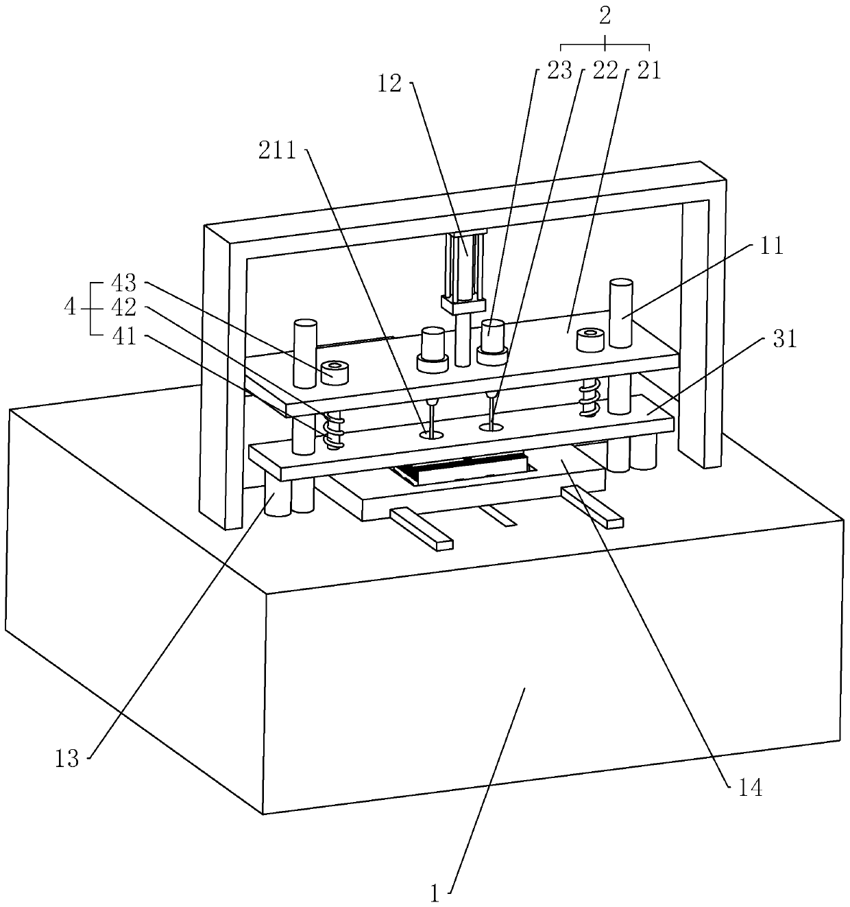
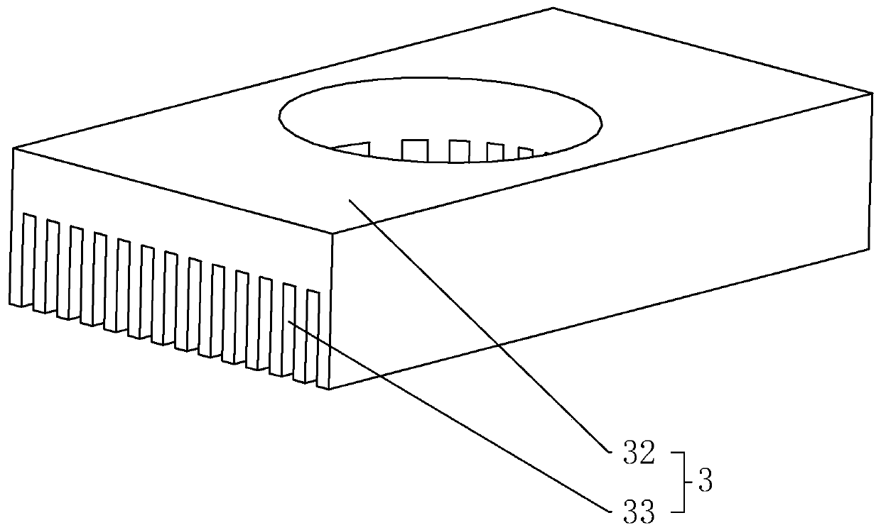
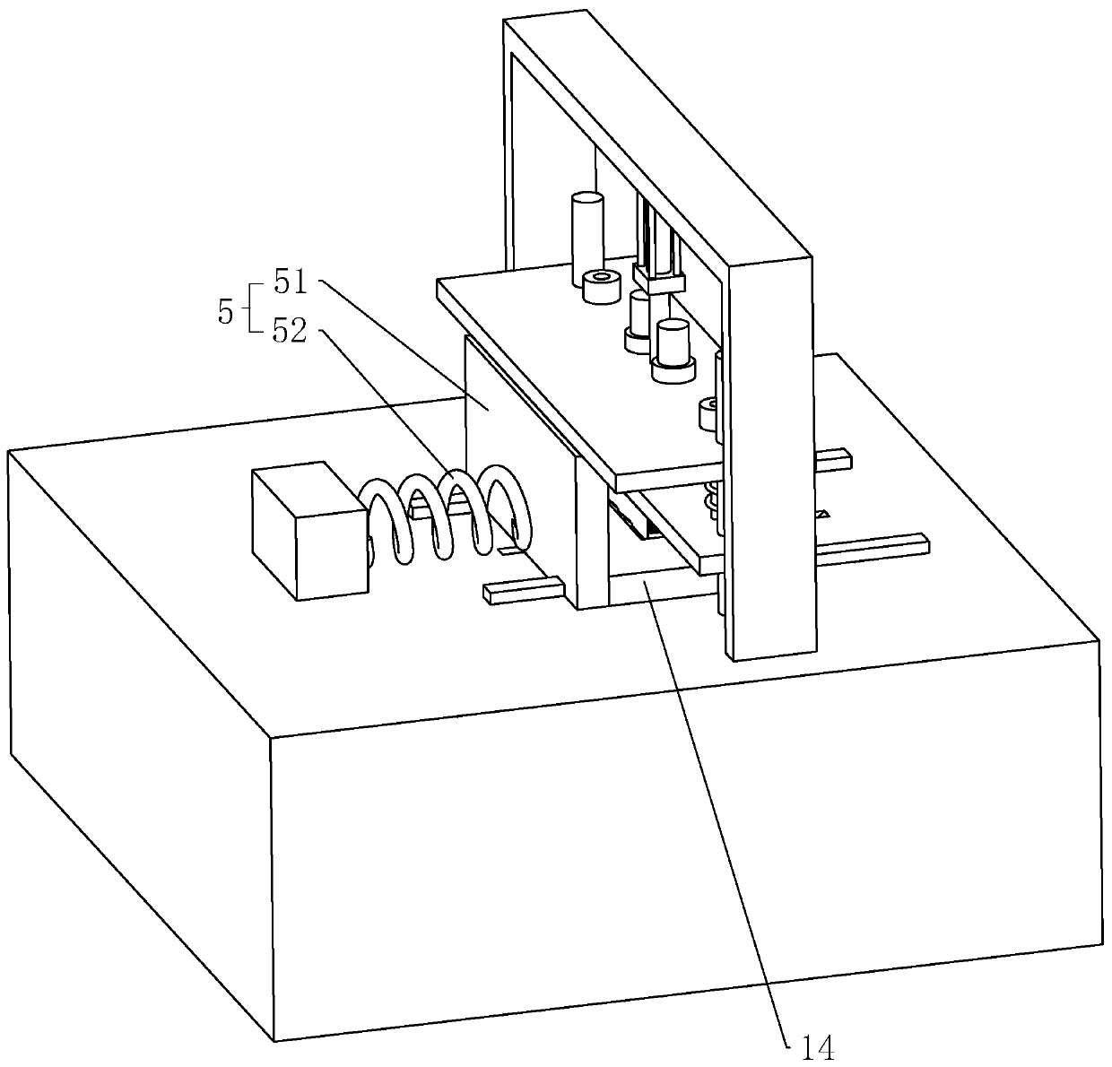
[0034] The invention discloses a cooling plate drilling equipment. When the cooling plate is drilled, the cooling fins connected to the cooling plate will not be twisted, so that the distance between adjacent cooling fins will not change, so that the cooling plate The heat dissipation effect will not be affected. like figure 1 As shown, it includes a frame body 1, a drilling mechanism 2 connected to the frame body 1, and a positioning mechanism 3 for positioning the heat sink. The drilling mechanism 2 includes a sliding base 21 that slides vertically along the frame body 1, two drill bits 22 that are rotatably connected to the lower end of the sliding base 21, and a motor 23 that drives the two drill bits 22 to rotate respectively. Both motors 23 are fixed with a reducer by bolts, and the reducer is fixed on the upper end of the sliding seat 21 by bolts. Th...


PUM


Abstract

The invention relates to drilling equipment for a heat dissipating plate. The drilling equipment comprises a frame body, a drilling mechanism connected to the frame body and a positioning mechanism for positioning the heat dissipating plate. The drilling mechanism comprises a sliding seat vertically moving along the frame body, at least one drill bit rotating at the lower end of the sliding seat and a motor for driving the drill bit to rotate. The positioning mechanism comprises a positioning seat vertically moving along the frame body, a positioning block arranged at the lower end of the positioning seat and multiple positioning pieces integrally formed at the lower end of the positioning seat. The positioning pieces are inserted between adjacent heat dissipating fins. The drilling mechanism is located at the upper end of the positioning mechanism, and the drill bit penetrates through the positioning seat, the positioning block and the positioning pieces to make contact with the heatdissipating plate. The positions of the heat dissipating fins are limited through the positioning pieces, the heat dissipating fins are not prone to twist distortion when machined, the intervals between the heat dissipating fins cannot be changed, and therefore the heat dissipating effect of the heat dissipating plate is not easily affected.

Description

technical field [0001] The invention relates to the technical field of heat dissipation plate processing equipment, in particular to a heat dissipation plate drilling equipment. Background technique [0002] There is an existing heat dissipation plate, which is integrally formed on the basis of the base plate with a number of heat sinks perpendicular to the base plate, leaving gaps between adjacent heat sinks, and when the heat sink is installed, it is necessary to process the through bolts on the surface of the heat sink. hole. [0003] A heat sink automatic drilling machine disclosed in Chinese patent CN205967504U, its technical points are: comprising a workbench, the workbench is provided with a feeding flow line, a blanking trough, a drilling device, a material suction mechanism, two positioning Pressing mechanism, two drilling stations; the suction mechanism is located above the drilling station, and the drilling device passes through the suction mechanism and points t...

Claims


Application Information

Patent Timeline
Patent Type & Authority Applications(China)
IPC IPC(8): B23B41/00B23Q3/00B23Q7/00
CPCB23B41/00B23Q3/00B23Q7/006
Inventor 杨同圣宋先彬罗石先罗小平
Owner 维迪兴业科技(深圳)有限公司
Why Eureka
Try Eureka