Biological drying aeration device

An aeration device and biological drying technology, applied in the direction of drying gas arrangement, drying, drying machine, etc., can solve the problems of increasing energy consumption, clogging of aeration holes, and reducing aeration effect, so as to promote the loss of water , improve the effect and ensure the effect of aeration effect

Pending Publication Date: 2020-08-28
ZHONGNONGXINKE SUZHOU ORGANIC RECYCLING RES INST CO LTD
View PDF0 Cites 7 Cited by
  • Summary
  • Abstract
  • Description
  • Claims
  • Application Information

AI Technical Summary

Problems solved by technology

[0003] The current bio-drying reactors for organic waste can be divided into two types according to the direction of the stirring axis, namely vertical stirring reactors (such as silo type) and non-vertical stirring reactors. The former stirring axis is perpendicular to the ground; the latter The stirring shaft is parallel to the ground or at a certain angle. Because the stirring shaft of this type of reactor is parallel to the ground or at a certain angle, the material will form a force on the aeration hole due to gravity and stirring, making the material very It is easy to enter the aeration hole and form a blockage of the aeration hole
After the aeration hole is blocked, the efficiency of the entire reactor will be reduced, which is not conducive to the realization of rapid biological drying
[0004] In the prior art, in order to prevent blockage, the aeration holes are either set on the side wall of the reactor or on the top of the reactor, but from the actual effect, the exposed gas may not enter the material in both solutions It is sucked away by the fan, which greatly reduces the effect of aeration and increases energy consumption

Method used


Image

  • Biological drying aeration device

Examples


Embodiment Construction

[0020] The technical solutions of the present invention will be further described below in conjunction with the accompanying drawings and embodiments.

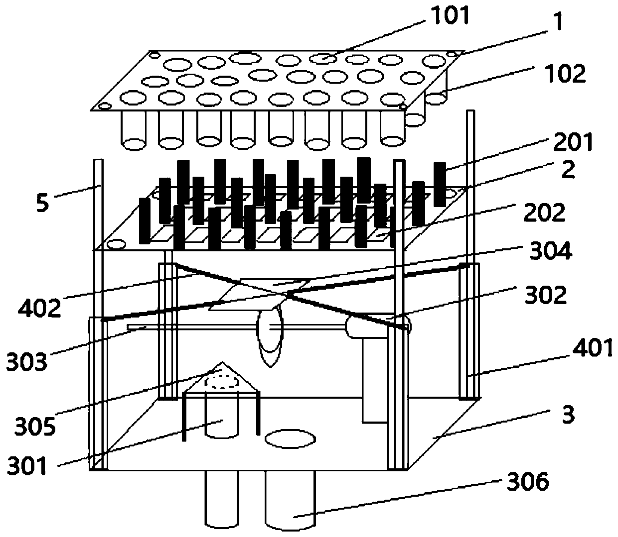
[0021] Such as figure 1 The biological drying aeration device shown includes an aeration panel 1 , a dredger panel 2 and a bottom tray 3 arranged sequentially from top to bottom, and the aeration panel 1 is placed at the bottom of the reactor. The entire aeration device is set in a sealed aeration box, located below the reactor. The aeration panel 1 is the upper bottom surface of the box body, and the bottom tray 3 is the lower bottom surface.

[0022] Several aeration holes 101 are arranged on the aeration panel 1 , and an aeration hole sleeve 102 is arranged under each aeration hole 101 .

[0023] A dredging plug 201 is set at the position corresponding to the aeration hole sleeve 102 on the said dredging plug panel 2, and the dredging plug 201 can pass through the aeration hole sleeve 102 from below to play the role of dr...


PUM


Abstract

The invention discloses a biological drying aeration device. The device comprises an aeration panel, a dredging bolt panel and a bottom tray. The aeration panel, the dredging bolt panel and the bottomtray are arranged from top to bottom. Aeration holes are formed in the aeration panel. Dredging bolts are arranged at the positions, corresponding to the aeration holes, of the dredging bolt panel, and dredging panel air outlets are further formed. An aeration pipe is arranged on the bottom tray and is used for conducting aeration to the top of the bottom tray. Meanwhile, a control motor and a camshaft which is horizontally placed are arranged, and the camshaft is driven by the control motor to rotate. An extrusion plate is arranged above a cam on the camshaft and fixed to the bottom tray through an elastic assembly. When the camshaft rotates, the extrusion plate moves upwards under the action of the cam and then moves downwards under the action of the elastic assembly, the extrusion plate and the dredging bolt panel are fixed, the extrusion plate and the dredging bolt panel simultaneously move up and down, and when the extrusion plate and the dredging bolt panel move upwards, the dredging bolts pass through the aeration holes to achieve dredging operation. According to the biological drying aeration device, the aeration function is fulfilled, the aeration holes can be effectivelyprevented from being blocked, and the aeration effect is guaranteed.

Description

technical field [0001] The invention relates to the technical field of organic waste treatment, in particular to a biological drying aeration device. Background technique [0002] In the biological drying process of organic waste treatment, in order to achieve the purpose of rapid material drying and water loss, the existing technology is to increase the aeration function in the reactor, and realize the gas entering from the bottom of the reactor by using an external air pump or fan. The reactor passes through the whole material, and the flow of gas in the whole process takes away the moisture in the material, making the material dry quickly. [0003] The current bio-drying reactors for organic waste can be divided into two types according to the direction of the stirring axis, namely vertical stirring reactors (such as silo type) and non-vertical stirring reactors. The former stirring axis is perpendicular to the ground; the latter The stirring shaft is parallel to the gro...

Claims


Application Information

Patent Timeline
IPC IPC(8): F26B11/18F26B21/00F26B25/00F26B25/02F26B25/18
CPCF26B11/18F26B21/001F26B25/003F26B25/02F26B25/18
Inventor 李季籍延宝
Owner ZHONGNONGXINKE SUZHOU ORGANIC RECYCLING RES INST CO LTD
Why Eureka
Try Eureka