
High-temperature air molten salt heat exchanger

A high-temperature air and heat exchanger technology, applied in the field of high-temperature waste heat recovery, can solve the problems of low efficiency and high energy consumption, and achieve the effects of improving heating efficiency, improving heat exchange efficiency, and strengthening heat exchange

Pending Publication Date: 2020-08-28
JIANGSU FEDERAL RESERVE ENERGY TECH CO LTD
View PDF0 Cites 1 Cited by
  • Summary
  • Abstract
  • Description
  • Claims
  • Application Information

AI Technical Summary

Problems solved by technology

[0005] It is precisely because of the defects of the existing molten salt heat exchanger that it takes multiple heat exchanges to raise the temperature of the molten salt to the required temperature, resulting in low efficiency and high energy consumption

Method used


Image

  • High-temperature air molten salt heat exchanger
  • High-temperature air molten salt heat exchanger
  • High-temperature air molten salt heat exchanger

Examples


Embodiment 1

[0034] The existing molten salt heat exchange device is a shell and tube type, see Figure 8 . The existing melting heat exchange device uses the heat of high-heat gas such as high-temperature tail gas generated in the industry to raise the temperature of the molten salt, thereby meeting the heating demand of the molten salt and making full use of the heat in the industrial tail gas.

[0035] Because the flow rate of molten salt is determined by the feed rate of molten salt. If the flow rate is too high, the heat exchange efficiency between the molten salt and the heat exchange tube will not be high, which not only affects the heating effect of the molten salt, but also has low utilization efficiency for the heat of the gas. If the flow rate is too slow, it is easy to cause the salt temperature to be too high, which will cause the molten salt to decompose.

[0036] Moreover, the existing molten salt heat exchange devices are often set Figure 8 The baffle plate marked A in . ...

Embodiment 2

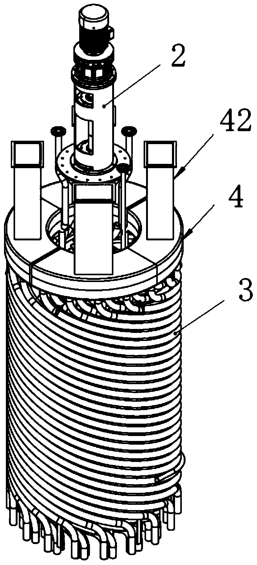
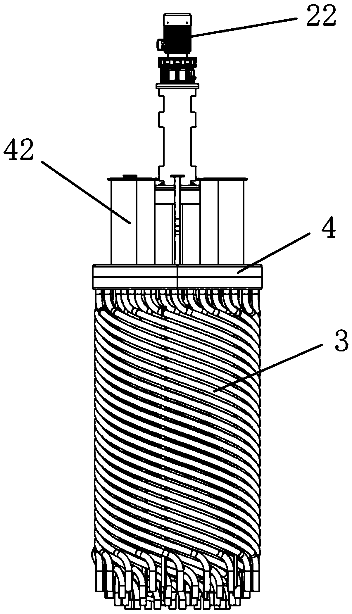
[0047]In the present invention, the heat exchange tube group includes multiple layers of heat exchange units radially distributed along the rotation axis of the stirring shaft; each heat exchange unit includes a plurality of heat exchange straight tubes distributed along the circumference of the rotation axis of the stirring shaft; The inlet of each is connected to the air inlet header, and the outlet of each heat exchange straight pipe is connected to the air collecting chamber.

[0048] Other technical characteristics are identical with embodiment 1.


PUM


Abstract

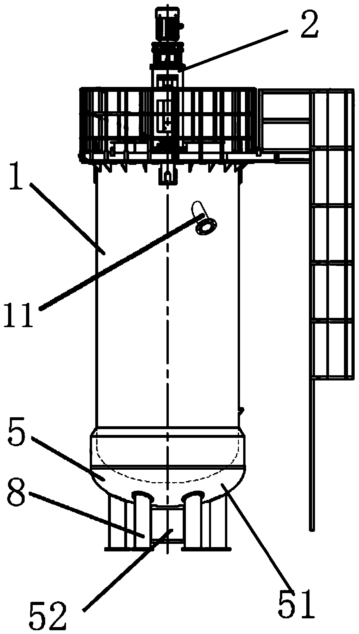
The invention relates to a high-temperature air molten salt heat exchanger which is provided with a container, a stirrer and a heat exchange pipe set. A molten salt inlet and a molten salt outlet areformed in the container, the stirrer comprises a driver for driving a stirring shaft, the driver is fixedly arranged on the container, and the stirring shaft extends into the container; the heat exchange pipe set comprises a plurality of heat exchange pipes, and gaps allowing molten salt to flow are formed between the heat exchange pipes; and the heat exchange pipe set is arranged outside the stirring shaft in a surrounding manner, and inlets and outlets of the heat exchange pipe set extend out of the container. The problems that when hot air in a conventional heat exchanger heats the molten salt, the energy density of the air side is low, the flow is large, the temperature difference between an inlet and an outlet of the molten salt side is large, the flow is small, consequently the flowspeed of the molten salt is too low, the viscosity of the molten salt is relatively high, heat is slowly taken away, and a molten salt side pipe wall film is high in temperature and easy to decomposeare effectively solved.

Description

technical field [0001] The invention relates to the field of high-temperature waste heat recovery, in particular to a high-temperature air molten salt heat exchanger. Background technique [0002] Molten salt has the advantages of large latent heat, high energy storage density, small undercooling, good thermal stability, wide heat storage and heat release temperature range, and low cost. Therefore, it is widely used as a heat storage medium for solar thermal utilization. During the use of molten salt, it needs to be heated in some links. The conventional molten salt heat exchange device is a shell and tube heat exchanger (see Figure 8 ), which mainly heats the molten salt and stores it in the salt tank through the heat source (hot air, high-temperature heat transfer oil, etc.) inside or outside the heat exchange tube. [0003] Because the flow rate of molten salt is determined by the flow rate of molten salt and the size of the flow section. In the case of constant flow ...

Claims


Application Information

Patent Timeline
Patent Type & Authority Applications(China)
IPC IPC(8): F28D7/02F28F13/12F28F27/00
CPCF28D7/024F28F13/125F28F27/00
Inventor 殷建平刘平心殷苏姜斌
Owner JIANGSU FEDERAL RESERVE ENERGY TECH CO LTD
Learn More