Magnetic powder flaw detection equipment for the Internet of Things

A technology of magnetic particle flaw detection and the Internet of Things, which is applied in the direction of material magnetic variables, complex mathematical operations, and adjustment of electrical variables, etc., can solve problems such as low accuracy of magnetizing current of flaw detection equipment, health damage of staff, and influence on other equipment. The effect of causing harm to the human body, improving safety, and improving accuracy

Active Publication Date: 2020-08-28
捷航设备制造股份有限公司
View PDF6 Cites 3 Cited by
  • Summary
  • Abstract
  • Description
  • Claims
  • Application Information

AI Technical Summary

Problems solved by technology

[0006] However, there are still three major problems in the current magnetic particle flaw detection machine. First, the accuracy of the magnetization current of the flaw detection equipment is low, and when the flaw detector magnetizes the workpiece to be tested, the time for the magnetization current to reach the specified current is too long, which will affect other equipment. It will cause damage to the workpiece; second, when performing magnetic particle flaw detection, due to the artificial addition of fluorescent magnetic powder, it will cause chronic health damage to the staff; third, many flaw detectors have errors in flaw detection, and the errors cannot be corrected in a timely manner. It is estimated that the effect of flaw detection will become worse

Method used


Image

  • Magnetic powder flaw detection equipment for the Internet of Things
  • Magnetic powder flaw detection equipment for the Internet of Things
  • Magnetic powder flaw detection equipment for the Internet of Things

Examples


Embodiment

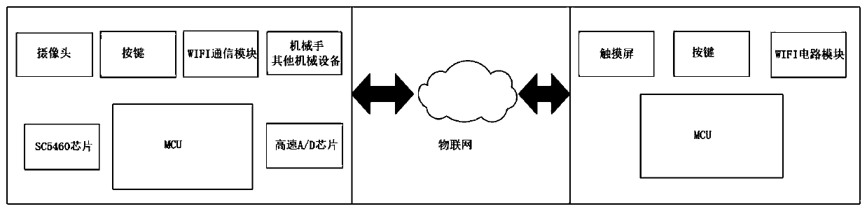
[0042] Embodiment: An Internet of Things magnetic particle flaw detection device, including a flaw detection main part and a remote control part.

[0043] 1. The main part of flaw detection

[0044] Such as figure 1 As shown, the main part of the flaw detection includes a magnetization current setting circuit, a magnetization control circuit, a two-way zero-crossing detection circuit, a remote communication module at the main body end, a camera, a mechanical arm, and a magnetic particle arrangement device.

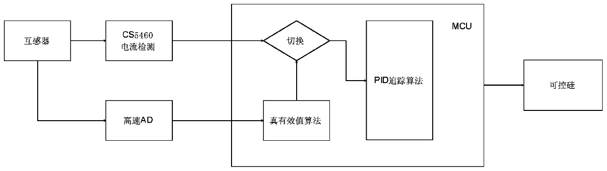
[0045] The magnetizing current setting circuit includes a first MCU, a transformer and a current detection chip connected in communication.

[0046] The transformer measures the magnetization current of the device under test. The current detection chip includes a large current detection chip and a small current detection chip. In this embodiment, the large current detection chip adopts CS5460, and the small current detection chip adopts ADC12DJ5200RF high-speed A / D chip, ...


PUM


Abstract

The invention discloses magnetic powder flaw detection equipment for the Internet of Things. The magnetic powder flaw detection equipment comprises a flaw detection main body part and a remote controlpart, the flaw detection main body part comprises a magnetization current setting circuit, a magnetization control circuit and a main body end remote communication module; the remote control part comprises a fourth MCU, a control end remote communication module and an input/output module, the fourth MCU is provided with two serial ports, one serial port is connected with the control end remote communication module, and the other serial port is connected with the input/output module. The magnetic powder flaw detection equipment disclosed by the invention realizes remote operation on the flaw detection equipment, and avoids health hazards possibly brought to an operator by manual close-range operation; in addition, the magnetizing current accuracy of the flaw detection equipment is improved, the time for magnetizing current to reach set current is shortened, and the influence of magnetization of the flaw detection equipment on other equipment or damage to workpieces is avoided.

Description

technical field [0001] The invention belongs to the technical field of detection, in particular to the technical field of magnetic particle flaw detection. Background technique [0002] At present, there are many detection methods for cracks and fracture defects in ferromagnetic materials, and the common ones are turbine method, ultrasonic wave and magnetic particle method. Among them, although the turbo method has a faster crack identification speed, its sensitivity is not high. Ultrasonic testing methods are not widely used due to their high cost. [0003] The magnetic particle inspection method is a detection method designed to detect whether there are defects such as cracks, breaks or impurities in the workpiece by using the principle of magnetic field adsorption of magnetic materials. Because the principle of this method is simple and the cost is low, but The accuracy of the results is high, so it has become the earliest non-destructive testing method applied in the i...

Claims


Application Information

Patent Timeline
Patent Type & Authority Applications(China)
IPC IPC(8): G01N27/84G05B19/042G05B11/42G05F1/56G01R19/25G06F17/16
CPCG01N27/84G01R19/2509G05B11/42G05B19/0421G05B19/0423G05B2219/21137G05B2219/2214G05B2219/25187G05F1/56G06F17/16
Inventor 李永建许怡航邵明智高虹卢倩夏晨洋卓悦田金辉
Owner 捷航设备制造股份有限公司
Why Eureka
Try Eureka