
The power supply circuit is suitable for aerospace application

A power supply circuit and circuit technology, applied in the direction of electrical components, output power conversion devices, and conversion equipment without intermediate conversion to AC, can solve problems such as limitations and achieve the effect of reducing the temperature rise of work

Pending Publication Date: 2020-08-28
中国电子科技集团公司第九研究所
View PDF0 Cites 2 Cited by
  • Summary
  • Abstract
  • Description
  • Claims
  • Application Information

AI Technical Summary

Problems solved by technology

[0006] The purpose of the present invention is to provide a solution to the problem of limited use of linear voltage regulator modules in some high power supply voltage occasions and the problem of derating use of components, improve the problem of temperature rise, reduce the size of the circuit board, reduce costs, and when When the single event lock-in effect occurs in the circuit, how to detect the fault and output the telemetry signal, and improve the space environment adaptability and reliability of the circuit. Power supply circuit suitable for aerospace applications

Method used


Image

  • The power supply circuit is suitable for aerospace application
  • The power supply circuit is suitable for aerospace application
  • The power supply circuit is suitable for aerospace application

Examples


Embodiment 1

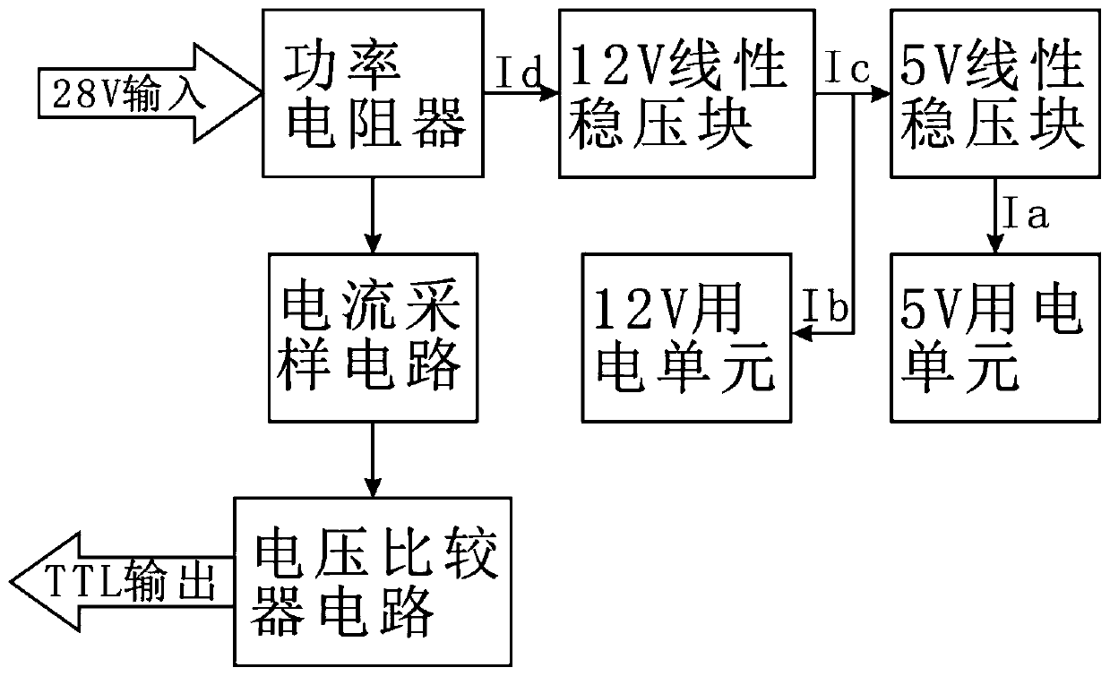
[0040] Embodiment 1: see Figure 1 to Figure 3, a power supply circuit suitable for aerospace applications, including a voltage input terminal, a 12V linear voltage stabilizing block, a 5V linear voltage stabilizing block, a 12V power consumption unit and a 5V power consumption unit, the 12V linear voltage stabilization block is connected to a 12V power consumption unit To supply power for it, the 5V linear voltage stabilizing block is connected to the 5V power consumption unit to supply power for it. The voltage input terminal is connected in series with the 12V linear voltage stabilizing block and the 5V linear voltage stabilizing block in sequence, and also includes a current sampling circuit and a voltage comparator circuit;

[0041] The voltage input terminal is used to input 20V-50V voltage;

[0042] It also includes a power resistor, a current sampling circuit and a voltage comparator circuit;

[0043] The power resistor is located between the voltage input terminal a...

Embodiment 2

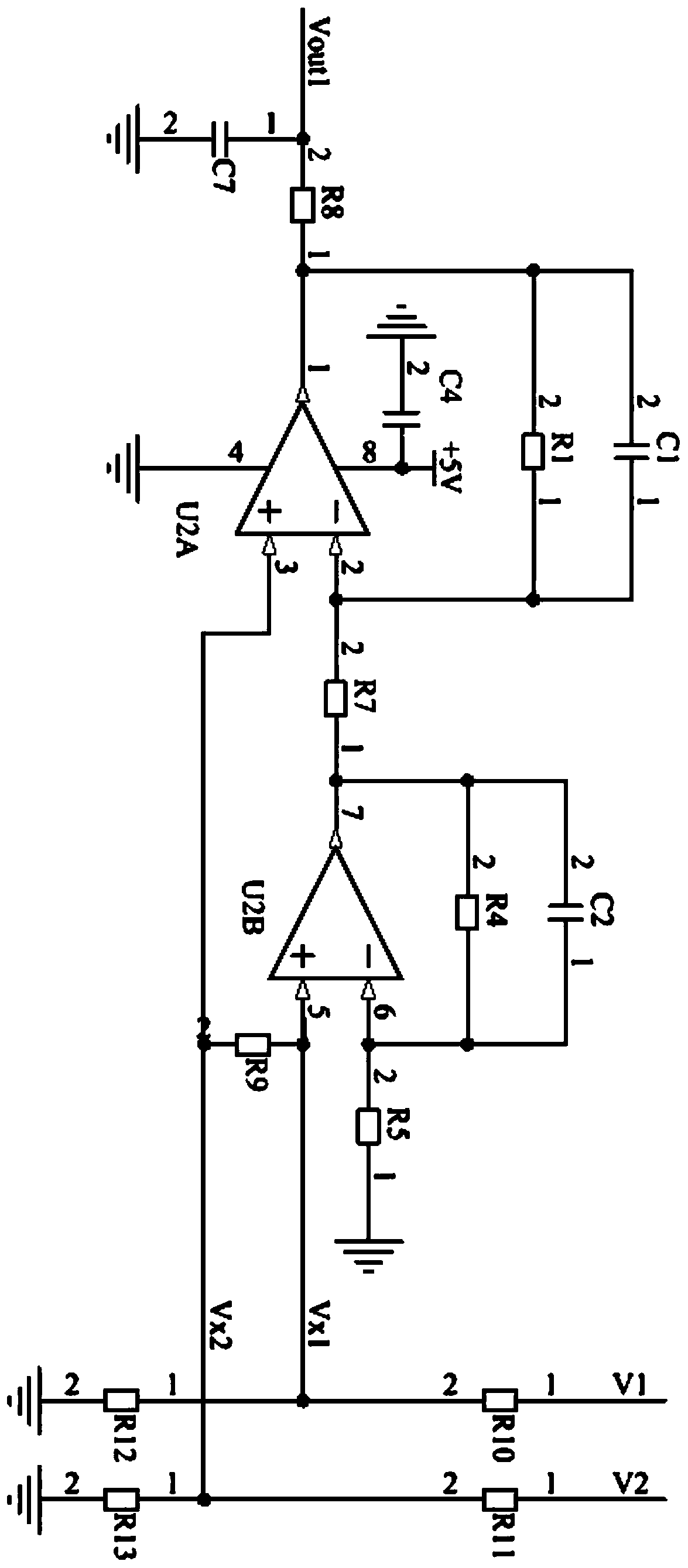
[0046] Example 2: see Figure 1 to Figure 3 , Embodiment 2 is improved on the basis of Embodiment 1. The power resistor is one or more chip resistors, and the current sampling circuit is a differential amplifier circuit composed of two operational amplifiers U2A and U2B. The current sampling circuit includes operational amplifiers U2A, U2B;

[0047] The positive input terminal of U2A is divided into two circuits, one is connected to the power resistor through the resistor R11, the other is grounded through the resistor R13, and the positive input terminal of U2B is also divided into two circuits, one is connected to the other of the power resistor through the resistor R10. One end, one path is grounded through resistor R12, and resistor R9 is also connected between the positive input terminals of U2A and U2B;

[0048] The reverse input terminal of U2A is divided into two routes, one route is connected to the output terminal of U2B through a resistor R7, and the other route is...

Embodiment 3

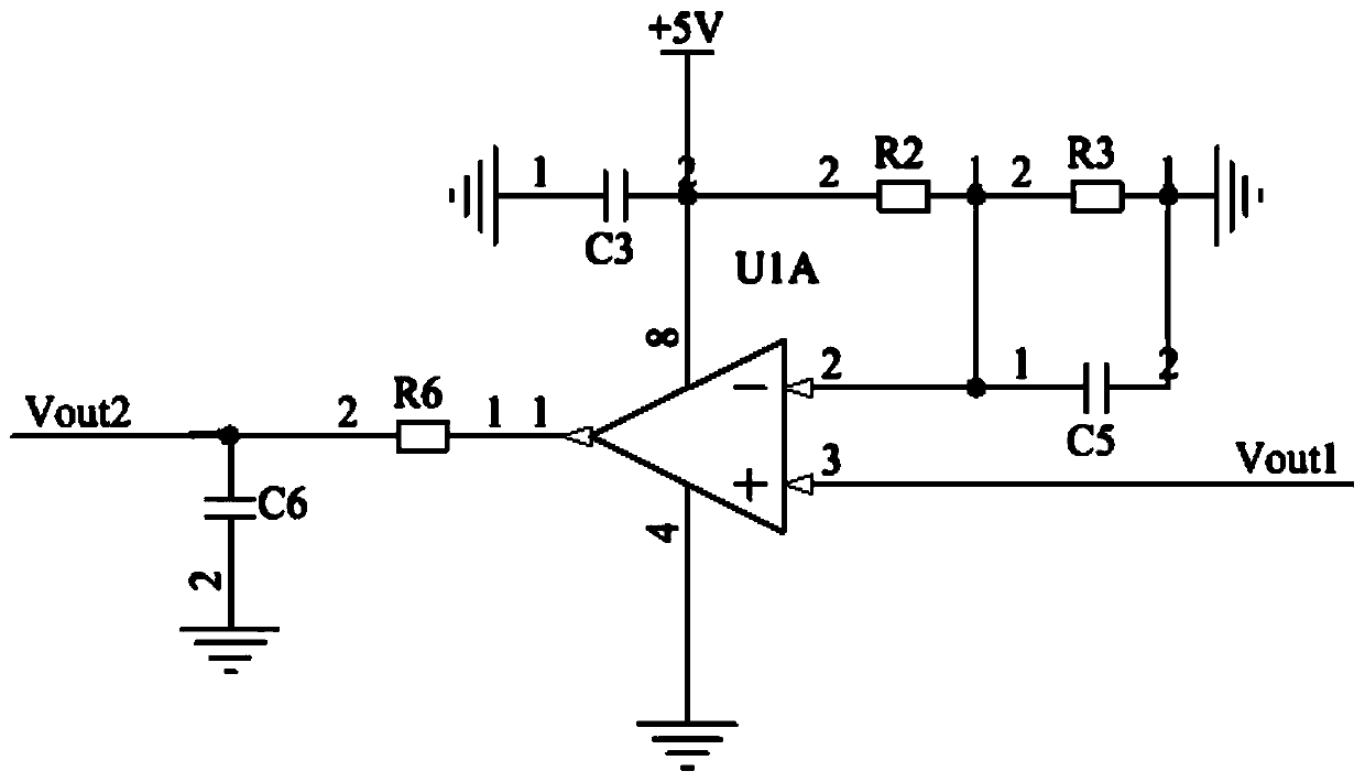
[0054] Embodiment 3: see Figure 1 to Figure 3 , in order to better illustrate the present invention, we define on the basis of Example 1.

[0055] see image 3 , in the figure R4=R7, R1=R5, R10=R11, R12=R13, R4=R7, where the current sampling circuit is connected in parallel to the voltage at the two terminals of the power resistor, we use Vx1 and Vx2 to denote respectively, the output terminal Voltage, represented by Vout1, Vout1=(Vx2-Vx1)*(R4+R5) / R4.

[0056] Assume that during normal operation, the current consumed by the 5V power unit is Ia=20mA, and the current consumed by the 12V power unit is Ib=30mA. Assume that the resistance of the power resistor is 100Ω, according to figure 1 We set the input voltage as +28V, then the current flowing through the 5V linear voltage regulator block is Ia=20mA, the current flowing through the 12V linear voltage regulator block is Ic=50mA, and the current flowing through the power resistor is Id=50mA. The voltage on the resistor is 10...


PUM


Abstract

The invention discloses a power supply circuit suitable for aerospace application. The circuit comprises a voltage input end, a 12V linear voltage stabilization block, a 5V linear voltage stabilization block, a 12V power utilization unit and a 5V power utilization unit, the circuit also comprises a power resistor, a current sampling circuit and a voltage comparator circuit, wherein the power resistor is used for limiting the current of a post-stage circuit, the current sampling circuit is used for collecting voltage at two ends of the power resistor and outputting sampling voltage after amplification, and the voltage comparator is respectively connected with the output of the current sampling circuit and preset reference voltage, compares the sampling voltage with the reference voltage andoutputs TTL level signals. According to the invention, the problem that the linear voltage regulator module does not meet the first-level derating requirement of aerospace parts is solved, the problem that the voltage regulator module is heated seriously is improved, and the problem of how to protect and detect when a single event locking effect occurs to a part of parts of a circuit is solved. And compared with a DC / DC voltage stabilizer module, the size is smaller, the weight is lighter, the cost is lower, and the space environment adaptability is better.

Description

technical field [0001] The invention relates to a power supply circuit, in particular to a power supply circuit suitable for aerospace applications. Background technique [0002] With the improvement of human living standards, more and more electronic devices appear, such as household appliances, handheld electronic devices, etc., which have become an indispensable part of our life. On the other hand, with the advancement of science and technology, humans begin to explore the mysteries of the universe, so space electronic equipment such as spacecraft, space stations, and communication satellites are also developing rapidly. [0003] However, no matter it is the electronic equipment on the ground or the electronic equipment in the space, the design of the power circuit is inseparable from the normal operation of the electronic equipment. Especially for electronic equipment in space, the design of its power supply system must not only work normally, but also must consider iss...

Claims


Application Information

Patent Timeline
Patent Type & Authority Applications(China)
IPC IPC(8): H02M3/06
CPCH02M3/06H02M1/0009H02M1/0045
Inventor 赵勇白雪闫欢彭根斋刘有彬唐宝权
Owner 中国电子科技集团公司第九研究所
Learn More