
PCBA assembly assembling method, assembling jig and PCBA assembly

An assembly method and jig technology, applied in the direction of electrical components, manufacturing tools, electrical components, etc., can solve the problem of reducing the safety and reliability of PCBA components, difficult to ensure the consistency of IPM module installation, and affecting the pin connection of IPM modules. and other problems, to achieve the effect of improving assembly efficiency and convenience, improving plug convenience and reliability, and reducing stress risk.

Active Publication Date: 2020-08-28
GUANGZHOU SHIYUAN ELECTRONICS CO LTD +1
View PDF8 Cites 2 Cited by
  • Summary
  • Abstract
  • Description
  • Claims
  • Application Information

AI Technical Summary

Problems solved by technology

[0004] In the PCBA assembly method provided by the prior art, because the IPM module is first locked with the heat sink, and then the IPM module is inserted on the PCB board, it is easy to cause visual interference due to the large volume of the heat sink compared with the IPM module, and affect the pins of the IPM module. Docking with the socket on the PCB board; because the wave soldering of the IPM module is performed first, and then the PCB board and the heat sink are locked, the IPM is easily affected by the wave impact during the wave soldering process, resulting in the IPM module after soldering The floating height makes it difficult to guarantee the installation consistency of the IPM module; at the same time, due to the floating height of the IPM module, the screw fixing force will be unbalanced when the radiator is locked, and there is a greater risk of stress, which reduces the PCBA components. safety and reliability of use

Method used


Image

  • PCBA assembly assembling method, assembling jig and PCBA assembly
  • PCBA assembly assembling method, assembling jig and PCBA assembly
  • PCBA assembly assembling method, assembling jig and PCBA assembly

Examples


Embodiment 1

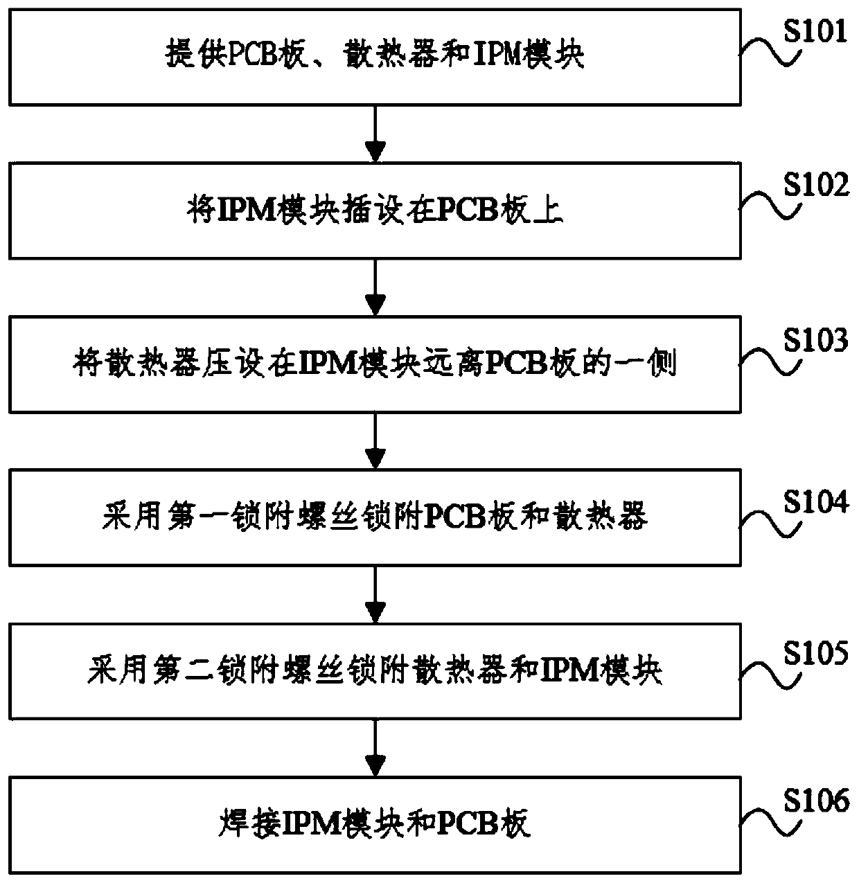
[0051] figure 1 The flowchart of the assembly method of the PCBA assembly provided for the embodiment of the present invention, such as figure 1 As shown, the embodiment of the present invention provides a method for assembling a PCBA assembly, which is used to assemble the IPM module and the heat sink in the PCBA assembly on the PCB board, so as to realize the modular assembly of the PCBA assembly.

[0052] Such as figure 1 As shown, the assembly method of the PCBA assembly provided by this embodiment includes the following steps:

[0053] Step S101, preparing PCB board, IPM module and radiator;

[0054] Step S102, inserting the IPM module on the PCB;

[0055] Step S103, pressing the radiator on the side of the IPM module away from the PCB board;

[0056] Step S104, using the first locking screw to lock the PCB board and the radiator;

[0057] Step S105, using the second locking screw to lock the radiator and the IPM module;

[0058] Step S106, welding the IPM module an...

Embodiment 2

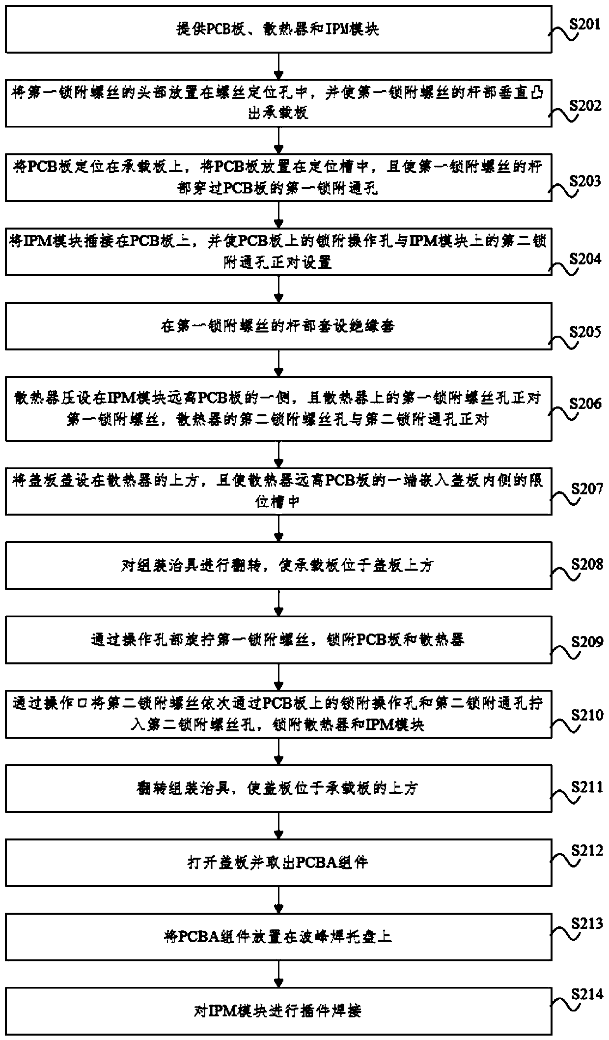
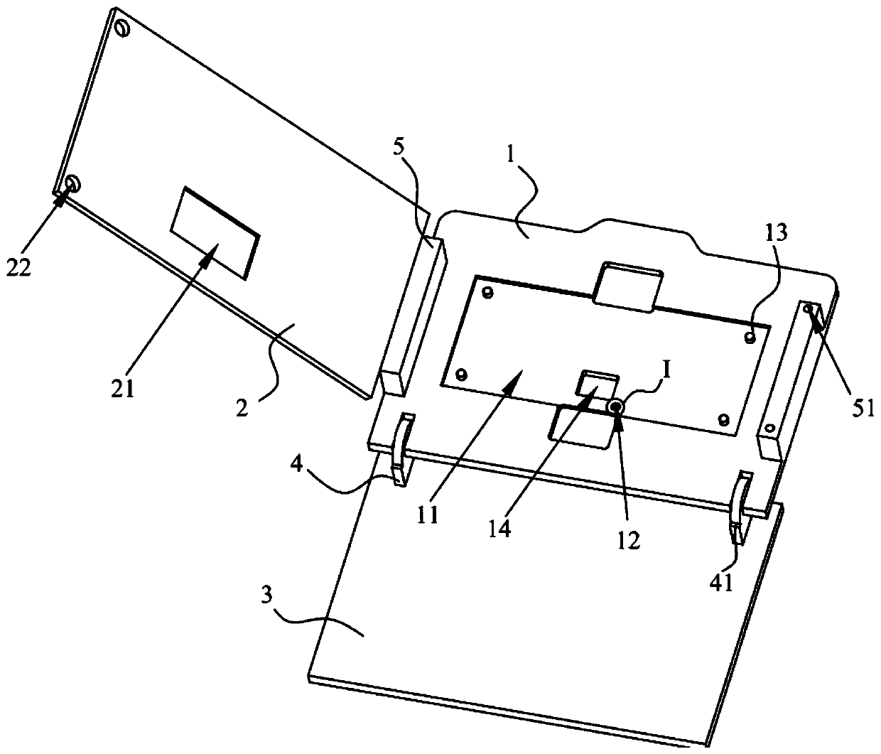
[0061] figure 2 It is a flow chart of the PCBA component assembly method provided by Embodiment 2 of the present invention, image 3 Schematic diagram of the structure of the assembly jig provided by the embodiment of the present invention, Figure 4 for image 3 Partial enlarged view of center I. Such as Figure 2-4 As shown, this embodiment provides a method for assembling PCBA components, which is a further refinement of the method for assembling PCBA components in Embodiment 1, and uses assembly jigs to assemble PCBA components.

[0062] Such as image 3 As shown, the assembly fixture includes a carrier plate 1 for carrying the PCB board. The carrier plate 1 is provided with a positioning groove 11 for positioning the PCB board. The bottom of the positioning groove 11 is provided with an operation port 14 for locking operation. The carrier plate 1 A screw positioning hole 12 is opened on the outside of the positioning groove 11.

[0063] Such as figure 2 As shown,...


PUM


Abstract

The invention belongs to the technical field of liquid crystal display, and particularly discloses a PCBA assembly assembling method, an assembling jig and a PCBA assembly. The assembling method comprises the steps of providing a PCB, a radiator and an IPM module; arranging the IPM module on the PCB in an inserted mode; pressing the radiator on the side, which is away from the PCB, of the IPM module; locking the PCB and the radiator by adopting a first locking screw; locking the radiator and the IPM module by adopting a second locking screw; and welding the IPM module and the PCB. The assembling jig is applied to the PCBA assembly assembling method, and the PCBA assembly is formed by adopting the PCBA assembly assembling method. According to the PCBA assembly assembling method, the assembling jig and the PCBA assembly provided by the invention, the assembling efficiency of the PCBA assembly can be improved, and the stress risk after the PCBA assembly is assembled is reduced.

Description

technical field [0001] The invention relates to the technical field of liquid crystal display, in particular to an assembly method of a PCBA assembly, an assembly jig and a PCBA assembly. Background technique [0002] With the continuous development of liquid crystal technology, liquid crystal display devices are widely used in fields such as computers, mobile phones, and televisions due to their advantages such as clear image display, no flicker, light weight, thin thickness, and low power consumption. [0003] In order to control and dissipate heat from the liquid crystal display device, the liquid crystal display device is usually provided with a PCBA assembly composed of components such as a PCB board, an IPM module, and a heat sink. When the existing PCBA components are soldered and assembled, the IPM module is first locked with the radiator, and then the IPM module is inserted on the PCB board, and then wave soldering is used to pass the IPM module through the pins on ...

Claims


Application Information

Patent Timeline
Patent Type & Authority Applications(China)
IPC IPC(8): H05K13/04B23P19/06
CPCH05K13/0465B23P19/06
Inventor 丁波
Owner GUANGZHOU SHIYUAN ELECTRONICS CO LTD
Learn More