Under-floor heating pipe cleaning sand recovery device and under-floor heating pipe cleaning device comprising same

A technology of recycling device and floor heating pipe, applied in the direction of cleaning heat transfer device, flushing, separation method, etc., can solve the problems of complicated operation, large cost investment, damage to the narrow bend of the pipeline, etc., so as to increase the filtering area and improve the filtering effect. , the effect of convenient system circulation

Pending Publication Date: 2020-09-01
精河县博润德建材商贸有限公司
View PDF6 Cites 2 Cited by
  • Summary
  • Abstract
  • Description
  • Claims
  • Application Information

AI Technical Summary

Problems solved by technology

The actual work has the following disadvantages: when the high-speed air in the pipeline drives the collodion in the pipe to clean the dirt, the collodion itself will not cause damage to the pipe wall due to its texture, but the dirt particles in the pipe after cleaning will inevitably have hard and sharp objects. Driven by the air, it will cause damage to the pipe and its narrow bends, resulting in water leakage and other consequences. Because of its certain plasticity, the collodion may be stuck in the narrow or bend of the pipe.
In actual work, it has the following disadvantages: the high-speed water flow cannot effectively clean the hard dirt on the pipe wall because of its relatively low friction, and the equipment is relatively complicated, and the cost investment for the cleaning result is too large
The actual work has the following disadvantages: the high-speed water flow cannot effectively clean the hard dirt on the pipe wall because of its relatively low friction, and the equipment is relatively complicated, and the cost investment for the cleaning result is too large
The actual work has the following disadvantages: the high-speed water flow cannot effectively clean the hard dirt on the pipe wall because of its relatively low friction, and there is no recovery device to damage the environment, and the equipment is relatively complicated, and the cost investment is too large for the cleaning result
[0008] Chinese patent CN206670447U discloses a cleaning device for floor heating pipes. Its working principle is to mix the cleaning sand in the liquid, and mix the cleaning sand in the water flow, so that the cleaning sand enters the pipeline, and the pipeline is cleaned by friction between the cleaning sand and the inner wall of the pipeline. , after the cleaning is completed, the cleaning sand is recycled through a rotating gauze, that is, the recycling gauze in the cleaning state and the recovery state needs to be rotated and switched, the actual operation is more complicated, and the rotating gauze is in the working state and the recovery state When switching, its wear resistance is also to be tested

Method used


Image

  • Under-floor heating pipe cleaning sand recovery device and under-floor heating pipe cleaning device comprising same
  • Under-floor heating pipe cleaning sand recovery device and under-floor heating pipe cleaning device comprising same
  • Under-floor heating pipe cleaning sand recovery device and under-floor heating pipe cleaning device comprising same

Examples


Embodiment 1

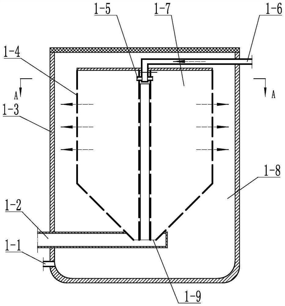
[0076] Embodiment 1: refer to Figure 1~2 , is a structural schematic diagram of Embodiment 1 of the present invention. This embodiment discloses a floor heating pipe cleaning sand recovery device, which includes a barrel body 1-3, and the barrel body 1-3 may be a cup-shaped body with an opening on the top , can also be a sealed cavity, the space surrounded by the barrel body 1-3 is provided with a filter screen 1-4, and the filter screen 1-4 can be surrounded by a water inlet 1-5 and The cavity of the sand discharge port 1-9, that is, the cavity surrounded by the filter screen is the filter cavity 1-7, and the interlayer sleeve 1-8 is between the outside of the filter screen cavity and the barrel body 1-3, and the filter screen 1 -4 can be a sealed filter cavity 1-7, or a cup-shaped body with an open upper part, the water inlet 1-5 is set on the upper part of the filter cavity 1-7, and the sand discharge port 1-9 is set at the filter cavity bottom of cavities 1-7,

[0077] ...

Embodiment 2

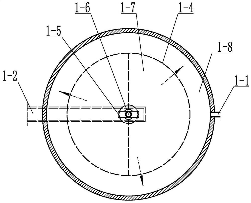
[0086] Embodiment 2: refer to image 3 , is a structural schematic diagram of Embodiment 2 of the present invention. Compared with Embodiment 1, the difference of this embodiment is that there are multiple filter chambers, that is, there are multiple filter chambers 1-7, and each filter chamber 1-7 is Water inlets 1-5 are provided, and water inlet pipes 1-6 are respectively connected with different water inlets 1-5.

[0087] In actual use: Since there are multiple filter chambers 1-7, the sand-water mixture can enter different filter chambers 1-7 through different water inlets 1-5, and in the same volume bucket, the filter screen is enlarged The filter area of ​​1-4 improves the filter effect and realizes the system circulation more conveniently.

[0088] Each individual filter cavity 1-7 may be a fan-shaped column, and a plurality of fan-shaped columns form a circular column.

[0089] It can also be a columnar body, and a plurality of columnar bodies form a columnar body. ...

Embodiment 3

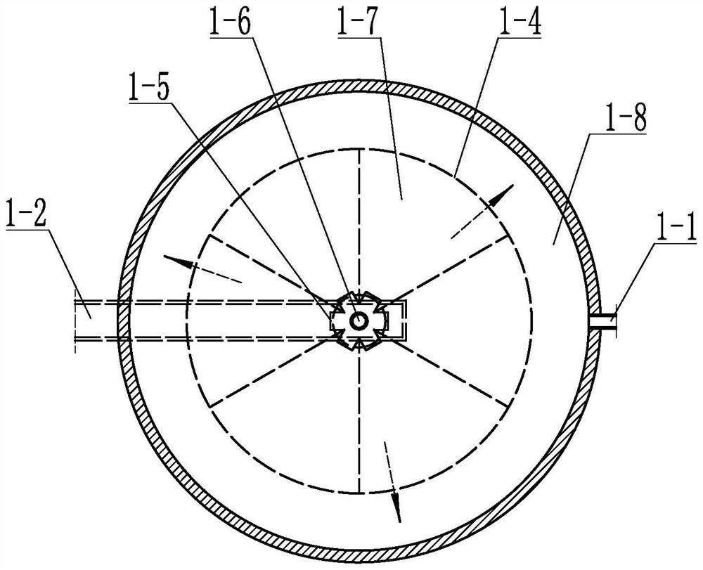
[0090] Embodiment 3: refer to Figure 4~6 , is a structural schematic diagram of Embodiment 3 of the present invention. Compared with Embodiment 1, the difference of this embodiment is that the water outlet direction of the water inlet 1-5 is formed by the surface tangent of the filter screen 1-4 of the filter chamber 1-7. The included angle is α, and α is 5 to 20 degrees.

[0091] In actual use: the sand-water mixture enters the filter chamber 1-7 through the water inlet pipe 1-6 and the water inlet 1-5. Since the water outlet direction of the water inlet 1-5 forms an angle with the surface of the filter screen 1-4, the sand and water mix The liquid can impact on the surface of the filter screen 1-4, and the mixed liquid entering the filter chamber 1-7 can form a swirling flow in the filter chamber 1-7, which improves the filtration efficiency of sand and water, and at the same time cleans the floor heating pipe 6 carried by the sand to be cleaned. The dirt inside can also b...


PUM


Abstract

The invention discloses an under-floor heating pipe cleaning sand recovery device. The device comprises a barrel body. The device is characterized in that: a filter screen is arranged in the barrel body; a cavity, namely, a filtering cavity, provided with a water inlet and a sand discharging opening is defined by the filter screen; an interlayer sleeve is arranged outside the filtering cavity; thedevice is also provided with a water outlet, a sand outgoing pipe and a water incoming pipe; the interlayer sleeve is communicated with the outside through the water outlet; one end of the sand outgoing pipe is connected with the sand discharging opening; the other end of the sand outgoing pipe is arranged outside the barrel body; one end of the water incoming pipe is connected with the water inlet; sand-water mixed liquid enters the filtering cavity through the water incoming pipe during cleaning; gravel is blocked by the filter screen, left in the filtering cavity and discharged through thesand discharging opening and the sand outgoing pipe; liquid penetrating through the filter screen is collected in the interlayer sleeve and discharged through the water outlet; and circulation is conducted in this way. Compared with the prior art, the device has the advantages of simple structure, good cleaning effect, convenience, practicability, convenience and quickness in cleaning sand recovery and the like.

Description

technical field [0001] The invention relates to a floor heating pipe cleaning sand recovery device and a floor heating pipe cleaning device. Background technique [0002] Compared with traditional heating, geothermal heating has the advantages of high heating efficiency, low water temperature attenuation rate, and uniform heating distribution. However, due to the relatively complicated pipeline arrangement, a large amount of metal ions (such as Ca, Mg) scale, sediment, and rust in the pipeline, resulting in pipeline blockage, poor water flow, and low heat dissipation efficiency. [0003] Chinese patent CN203991551 discloses a physical floor heating cleaning device. Its working principle is to use a positive pressure air pump to input air from the inlet of the pipeline to drive the collodion particles to remove the dirt on the inner wall of the pipeline through friction in the cleaned pipeline, and pass through the pipeline outlet. The negative pressure air pump and the posi...

Claims


Application Information

Patent Timeline
Patent Type & Authority Applications(China)
IPC IPC(8): B01D29/35B01D29/90B01D29/92B01D29/94F28G9/00
CPCB01D29/35B01D29/90B01D29/92B01D29/94F28G9/00
Inventor 董焕金
Owner 精河县博润德建材商贸有限公司
Why Eureka
Try Eureka