Automatic discharge device of electric conveying frame

A technology of automatic unloading and conveying racks, which is applied in the field of conveying racks, can solve the problems of automatic unloading, time-consuming loading and unloading, etc., and achieve the effects of preventing losses, improving the degree of automation, and saving time

Inactive Publication Date: 2020-09-01
山东方通智能科技有限公司
View PDF5 Cites 2 Cited by
  • Summary
  • Abstract
  • Description
  • Claims
  • Application Information

AI Technical Summary

Problems solved by technology

[0004] The technical problem solved by the present invention is to overcome the time-consuming and labor-intensive loading and unloading of t

Method used


Image

  • Automatic discharge device of electric conveying frame
  • Automatic discharge device of electric conveying frame
  • Automatic discharge device of electric conveying frame

Examples


Embodiment Construction

[0024] The following will clearly and completely describe the technical solutions in the embodiments of the present invention with reference to the accompanying drawings in the embodiments of the present invention. Obviously, the described embodiments are only some, not all, embodiments of the present invention. Based on the embodiments of the present invention, all other embodiments obtained by persons of ordinary skill in the art without making creative efforts belong to the protection scope of the present invention.

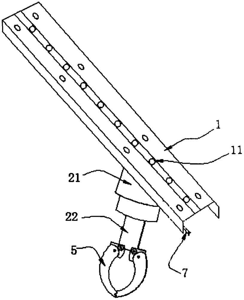
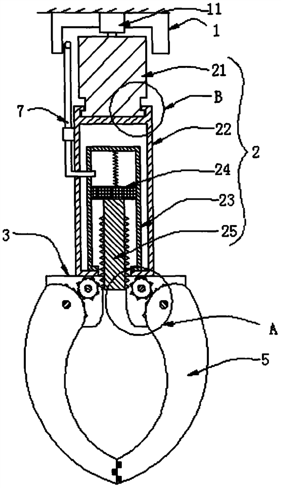
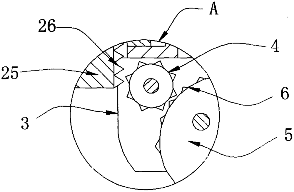
[0025] see Figure 1-4 , the present invention provides a technical solution: the automatic unloading device of the electric conveyor frame includes a conveyor rail frame 1, the conveyor rail frame 1 is fixedly installed on the wall, and a drive chain 11 is installed in the inner cavity of the conveyor rail frame 1, and the drive chain 11 It is driven by a stepping motor, and the stepping motor is electrically connected to the cylinder. When the stepping motor...


PUM


Abstract

The invention discloses an automatic discharge device of an electric conveying frame. The automatic discharge device comprises a conveying guide rail frame, a driving chain, a linkage structure, clamping arms, an arc-shaped gear and a conveying air pipe. A material can be clamped and discharged automatically and rapidly by electrically connecting a cylinder with the linkage structure, not only istedious manual operation avoided, but also time is saved, the conveying and discharging efficiency of the electric conveying frame is improved, and long-term conveying work is facilitated; a steppingmotor drives the driving chain and is electrically connected with the cylinder, so that workers can automatically control the driving chain to start or stop and control the conveying and discharging work of the cylinder, and the automatic degree of the conveying frame is improved; and by means of protruding blocks on the inner sides of the clamping arms, the friction force between the two clampingarms and the material can be increased, and the loss caused by falling in the clamping and conveying process is avoided.

Description

technical field [0001] The invention relates to the technical field of conveying racks, in particular to an automatic unloading device for electric conveying racks. Background technique [0002] The conveying system can realize the long-distance conveying of goods. The conveying system is composed of multiple horizontal lines. The structure of the transverse lines includes a driving mechanism and a guide rail. The driving mechanism located on the upper side of the guide rail is arranged horizontally. On the guide rail, the driving mechanism pushes the shelf hook to slide on the guide rail to realize the delivery of goods. The guide rails and driving mechanism are normally set up elevated, and the existing transverse lines often build a conveying system on the same level, and the guide rails in each transverse line are connected together. [0003] The existing horizontal line needs to realize the lifting of the shelf through the vertical line before realizing the shelf trans...

Claims


Application Information

Patent Timeline
IPC IPC(8): B23Q7/04
CPCB23Q7/04
Inventor 张蒲
Owner 山东方通智能科技有限公司
Why Eureka
Try Eureka