
Dielectric waveguide filter

A dielectric waveguide and filter technology, which is applied in the field of dielectric waveguide filters, can solve the problems of high requirements on the actual structure of dielectric waveguide filters and the difficulty of realizing dielectric waveguide filters, etc., to improve out-of-band suppression performance, reduce depth, The effect of reducing complexity

Inactive Publication Date: 2020-09-01
AAC PRECISE MFG TECH CHANGZHOU
View PDF8 Cites 2 Cited by
  • Summary
  • Abstract
  • Description
  • Claims
  • Application Information

AI Technical Summary

Problems solved by technology

[0003] Although the dielectric waveguide filter has the above advantages, most of the current dielectric waveguide filters are integrally dry-pressed. Therefore, the actual structure of the dielectric waveguide filter is relatively high. Some structures that can be easily realized in a metal cavity, Difficult to realize in dielectric waveguide filter

Method used


Image

  • Dielectric waveguide filter
  • Dielectric waveguide filter
  • Dielectric waveguide filter

Examples


Embodiment Construction

[0022] It should be noted that, in the case of no conflict, the embodiments in the present application and the features in the embodiments can be combined with each other. The present invention will be described in detail below with reference to the accompanying drawings and examples.

[0023] It should be pointed out that the following detailed description is exemplary and intended to provide further explanation to the present application. Unless defined otherwise, all technical and scientific terms used herein have the same meaning as commonly understood by one of ordinary skill in the art to which this application belongs.

[0024] It should be noted that the terminology used here is only used to describe specific implementations, and is not intended to limit the exemplary implementations according to the present application. As used herein, unless the context clearly dictates otherwise, the singular is intended to include the plural, and it should also be understood that ...


PUM


Abstract

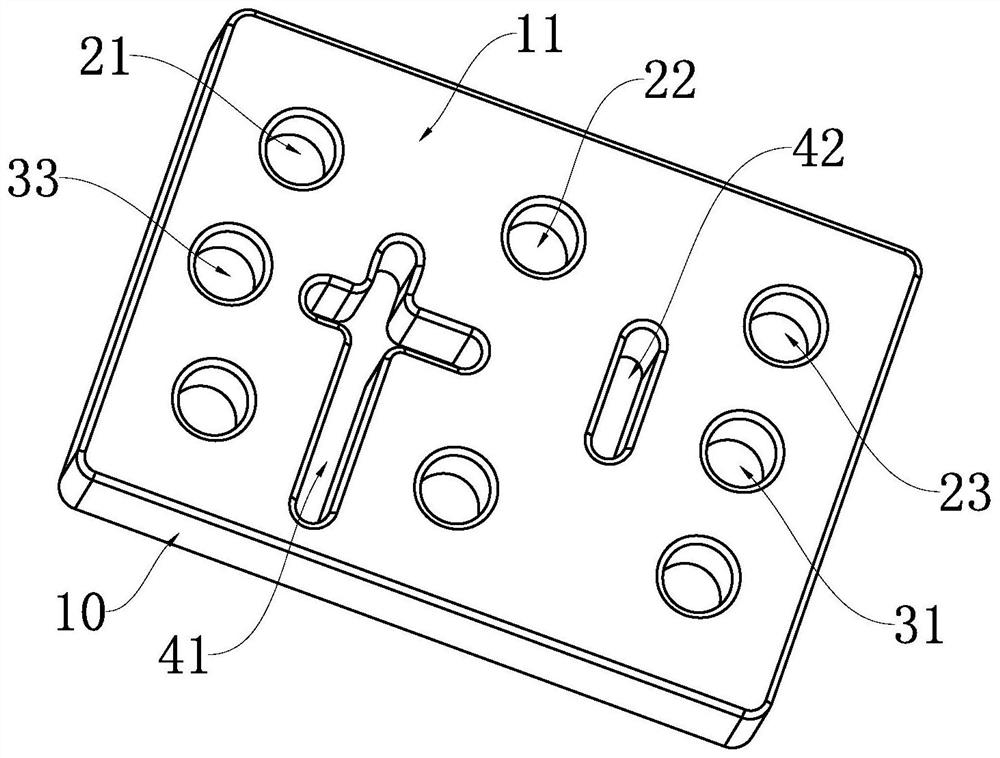
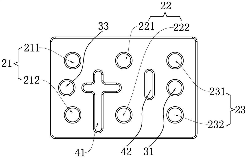
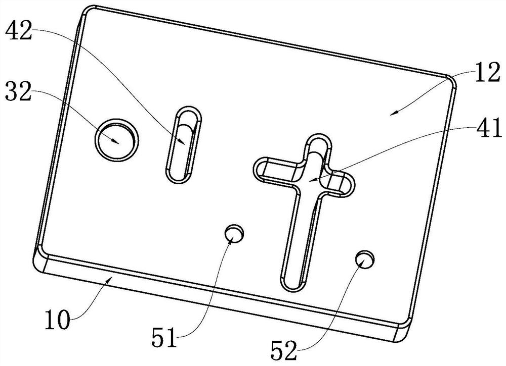
The invention relates to the technical field of filters, and provides a dielectric waveguide filter. The filter comprises a dielectric body, the dielectric body comprises a first surface and a secondsurface, the first surface is provided with a plurality of groups of resonance parts, each group of resonance parts comprises two resonance blind holes which are symmetrically arranged, and a first coupling blind hole is arranged between the two resonance blind holes of one group of resonance parts; the second surface is provided with a second coupling blind hole, the central axis of the first coupling blind hole coincides with the central axis of the second coupling blind hole, and the first coupling blind hole and the second coupling blind hole form a capacitive coupling structure. By applying the technical scheme, the first coupling blind hole and the second coupling blind hole which are symmetrical up and down generate a pair of zero points, so that the out-of-band rejection performance can be improved; and meanwhile, the depth of the first coupling blind hole is reduced and is basically consistent with the hole depth of the resonance blind hole, so that the number of pressing punches can be reduced, and the complexity of a filter mold is reduced.

Description

【Technical field】 [0001] The invention relates to the technical field of filters, in particular to a dielectric waveguide filter. 【Background technique】 [0002] In the 5G era, limited by the requirements of Massive MIMO (large-scale antenna technology) for large-scale antenna integration, filters need to be more miniaturized, integrated, and lightweight. In the case of limited size, due to their own material loss, traditional metal cavity filters and dielectric resonant cavity filters cannot achieve high Q values ​​(Q values ​​represent loss / input power), resulting in various Performance metrics are limited. The ceramic dielectric waveguide filter has no metal cavity because the electromagnetic wave resonance occurs inside the dielectric material, and the dielectric constant of its own material is generally 20-50, so the volume will be smaller. At the same time, the ceramic dielectric waveguide filter has the advantages of high Q value, good frequency selection characteri...

Claims


Application Information

Patent Timeline
Patent Type & Authority Applications(China)
IPC IPC(8): H01P1/20
CPCH01P1/2002
Inventor 李陆龙姜华韩莉岳月华
Owner AAC PRECISE MFG TECH CHANGZHOU
Learn More